Intravascular bifurication zone implants and crimping and deployment methods thereof

Active Publication Date: 2018-09-18
BERNSHTEIN VADIM
View PDF9 Cites 0 Cited by
  • Summary
  • Abstract
  • Description
  • Claims
  • Application Information

AI Technical Summary

Benefits of technology

This patent describes a method for delivering and deploying multiple stents in a patient with an intravascular bifurcation zone, including a main blood vessel and a side blood vessel. A catheter is used to crimp and deploy the stents in a controlled manner. The technical effect is improved blood flow and reduced likelihood of complications in cases where multiple stents are needed to repair damaged blood vessels. The method can be used in an endovascular aneurysm repair procedure and makes the procedure faster and more effective.

Problems solved by technology

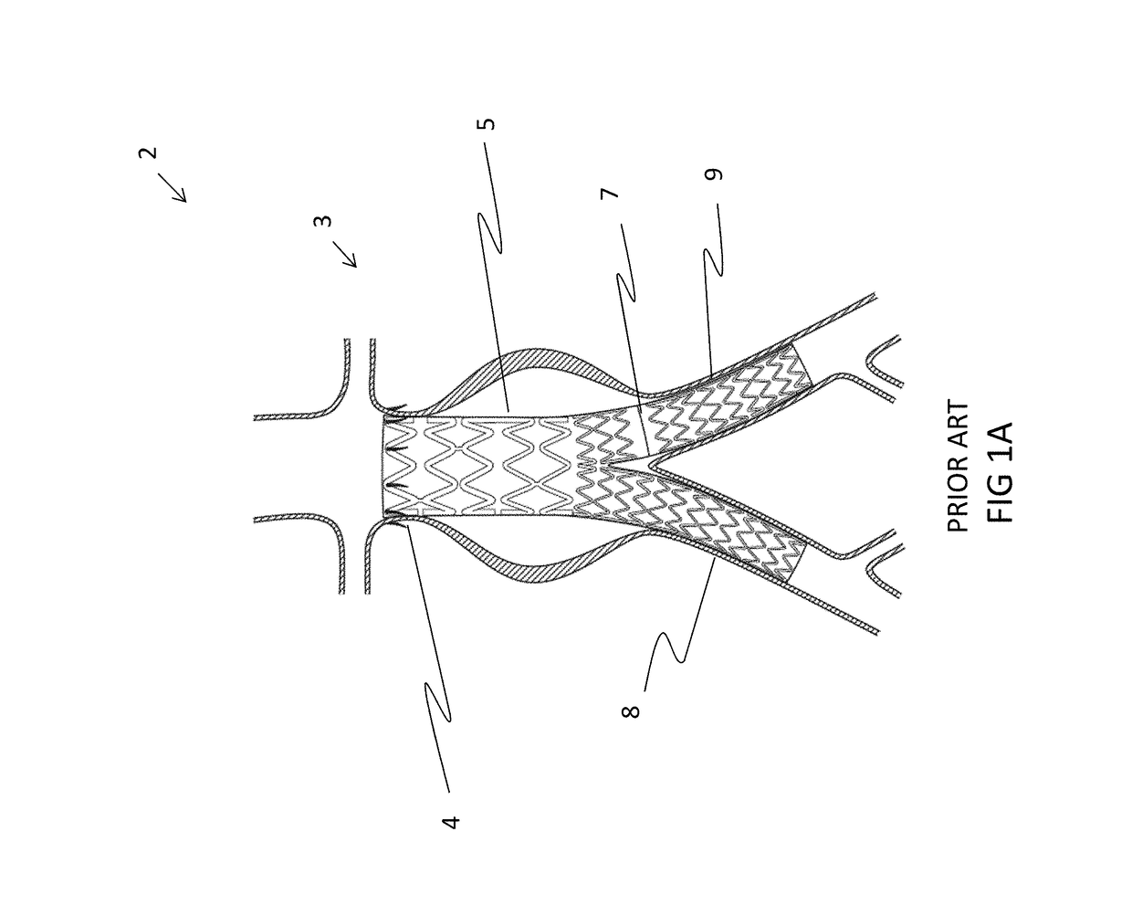
Conventional stents have been used with limited success rates for treating more complex vascular problems, such as lesions at or near bifurcation zones.
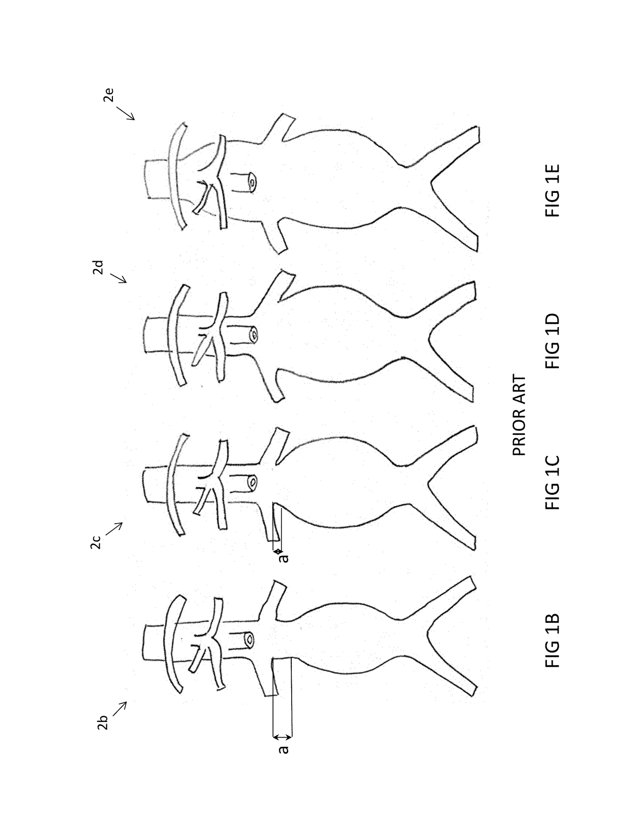
As such, the variations of typical aortic renal zone configuration corresponding to Juxtarenal, Pararenal, and Suprarenal AAA's are increasingly difficult / improbable choices for such repairs.
However custom-made implants have significant disadvantages such as, but not limited to: higher fabrication cost; and very long lead times to fabricate / fit the implant, as fabrication of custom-made implants involves time-consuming iterations between the manufacturer and physician, and the need for multiple CT scans of the patient—all additionally contributing to cost.
Off-the-shelf implants, on the other hand, generally address one or more “average” physiological bifurcation configurations—affording relatively lower fabrication cost and much quicker availability but not necessarily an optimal / custom fit—a point which is discussed further hereinbelow.
Prior art implant techniques in bifurcation zones are limited by catheter flexibility and rigidity, which subsequently impact the rigidity and length of a crimped implant device inside the sheath of the catheter.
Another limitation in prior art 
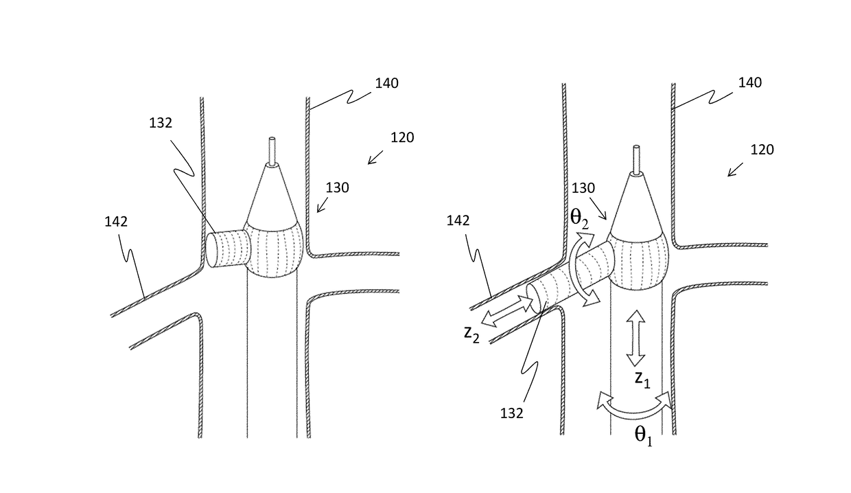
branch side stents or main stent frame extensions is that they typically address bifurcation inclinations of less than 70 degrees relative to the central axis of the main vessel.
In cases where bifurcation inclinations exceed 70 degrees (ie approaching the normal, meaning 90 degrees) implant techniques become excessively complicated—as the catheter and its payload would be subject to relatively sharp bending.
In addition to mechanical limitations imposed by crimping on prior art stents, inclusion of excessively-crimped prior art stents, combined with relatively sharp bending of the catheter can lead to mechanical fatigue / failure of the stent and thus pose excessive risk in such procedures and / or over time.
In addition to the limitations noted above, when the implant is deployed (including the side stent) the overall, final implant configuration can be exposed to material fatigue, as the bifurcation angle predisposes the side stent to strut fracture.
In such a configuration, deployment of a side stent is typically more complicated, for reasons as noted hereinabove.
In renal artery-related procedures, blood flow may be temporarily limited, but only for short periods.
Implant producers are faced with formidable challenges to support all sizes / scales of vessels having variable amorphic geometries, varying from patient-to-patient—all in addition to addressing parameter changes, as discussed further hereinbelow.
Some factors adding to complexity in a procedure are:long procedure time—ie long chronology—with a typical total operation time between 2 to 3 hours and fluoroscopy time between 50-70 minutes;involvement of support equipment for a FEVAR procedure (such as: a multi-sheath introducer, a marker catheter, and dedicated post dilatation balloons); andmultiple renal artery approaches for complex angularity cases (such as through brachiocephalic and left subclavian arteries) with accompanying increased risk of an ischemic stroke.
In addition to the risk and complexity elements noted hereinabove, the variation of different products from different vendors and of the deployment and fixation of each component in a procedure can contribute to unpredictability of functionality of a complete implant—again exacerbating overall cost and / or risk.
As observed in the procedures outlined above, off-the-shelf implants have integrated lateral fenestrated apertures not necessarily custom-fit to the patient.
As such, it may be summarized that current prior art implant procedures have risks, complexity, and expenses, along with concomitant long procedural chronologies.

Method used


Image

  • Intravascular bifurication zone implants and crimping and deployment methods thereof
  • Intravascular bifurication zone implants and crimping and deployment methods thereof
  • Intravascular bifurication zone implants and crimping and deployment methods thereof

Examples


Embodiment Construction

[0091]Embodiments of the present invention relate to intravascular bifurcation zone implants and crimping and deployment methods thereof. Furthermore, embodiments of the current invention are applicable to deployment of an implant for bifurcation inclinations greater than 70 degrees relative to the central axis of the main vessel (ie approaching the normal, meaning 90 degrees) and / or when the ratio of the main vessel diameter to at least one secondary vessel diameter is greater than 2.

[0092]Embodiments of the current invention provide for novel crimping and deployment techniques for bifurcation stents and temporary embolic protection devices as part of the complex scaffolding that includes a main vessel device which supports branch components / side stents for passive and active functional use.

[0093]Embodiments of the current invention include stent configurations and crimping processes thereof which enable transforming an initial / deployed cylindrical shape of a stent to a crimped, cu...


PUM


Abstract

A multi stent delivery system for intravascular bifurcation zone delivery and deployment of a multi stent, the bifurcation zone having a main blood vessel, the main blood vessel having a main blood vessel longitudinal axis and at least one side blood vessel inclined / branching out of the main blood vessel, the delivery system comprising: a catheter having a catheter longitudinal axis substantially coaxial with the main blood vessel longitudinal axis, a tube positioned coaxially within the catheter, the catheter having a distal end and a proximal end, and the tube containing: at least one crimped side stent for deployment substantially normal to the catheter longitudinal axis and into the side blood vessel; and at least one crimped main stent for deployment substantially along the catheter longitudinal axis into the main blood vessel; wherein the at least one crimped side stent and at least one crimped main stent are part of a unified / singular configuration within a sheath, located substantially at the distal end.

Description

[0001]The present application claims priority from U.S. Provisional Application No. 62 / 502,770, filed 8 May 2017, whose disclosure is incorporated herein by reference.FIELD OF THE INVENTION AND BACKGROUND[0002]The current invention relates to medical stents in general, and specifically to intravascular bifurcation zone implants and crimping and deployment methods thereof. In the specification and claims which follow hereinbelow, the term “implant” is a general term, interchangeable with “intravascular device”—both terms herein intended to mean “stent-graft”—as known in the art. The terms “bifurcation zone” and “bifurcation”, and variations thereof, as used in the specification and claim which follow hereinbelow, are intended to mean points / places / zones in the vascular system where at least one secondary / side blood vessel branches out of a typically larger, main artery / blood vessel.[0003]The term “delivery system”, as used in the specification and claims which follow hereinbelow, is ...

Claims


Application Information

Patent Timeline
IPC IPC(8): A61F2/954A61F2/07A61F2/962A61F2/06
CPCA61F2/954A61F2/07A61F2/962A61F2002/077A61F2002/061A61F2002/065A61F2220/0016A61F2/856A61F2/88A61F2/885A61F2250/0048A61F2250/006
Inventor BERNSHTEIN, VADIM
Owner BERNSHTEIN VADIM
Why Eureka
Try Eureka