Current resonant type DC voltage converter, control integrated circuit, and current resonant type DC voltage conversion method
a technology of current resonant type and dc voltage, which is applied in the direction of electric variable regulation, process and machine control, instruments, etc., can solve the problems of increasing the number of switching elements, increasing the loss in the compensation circuit, and difficulty in achieving high efficiency, so as to reduce various kinds of losses, improve efficiency, and the effect of present invention
- Summary
- Abstract
- Description
- Claims
- Application Information
AI Technical Summary
Benefits of technology
Problems solved by technology
Method used
Image
Examples
first modification example
of the First Embodiment
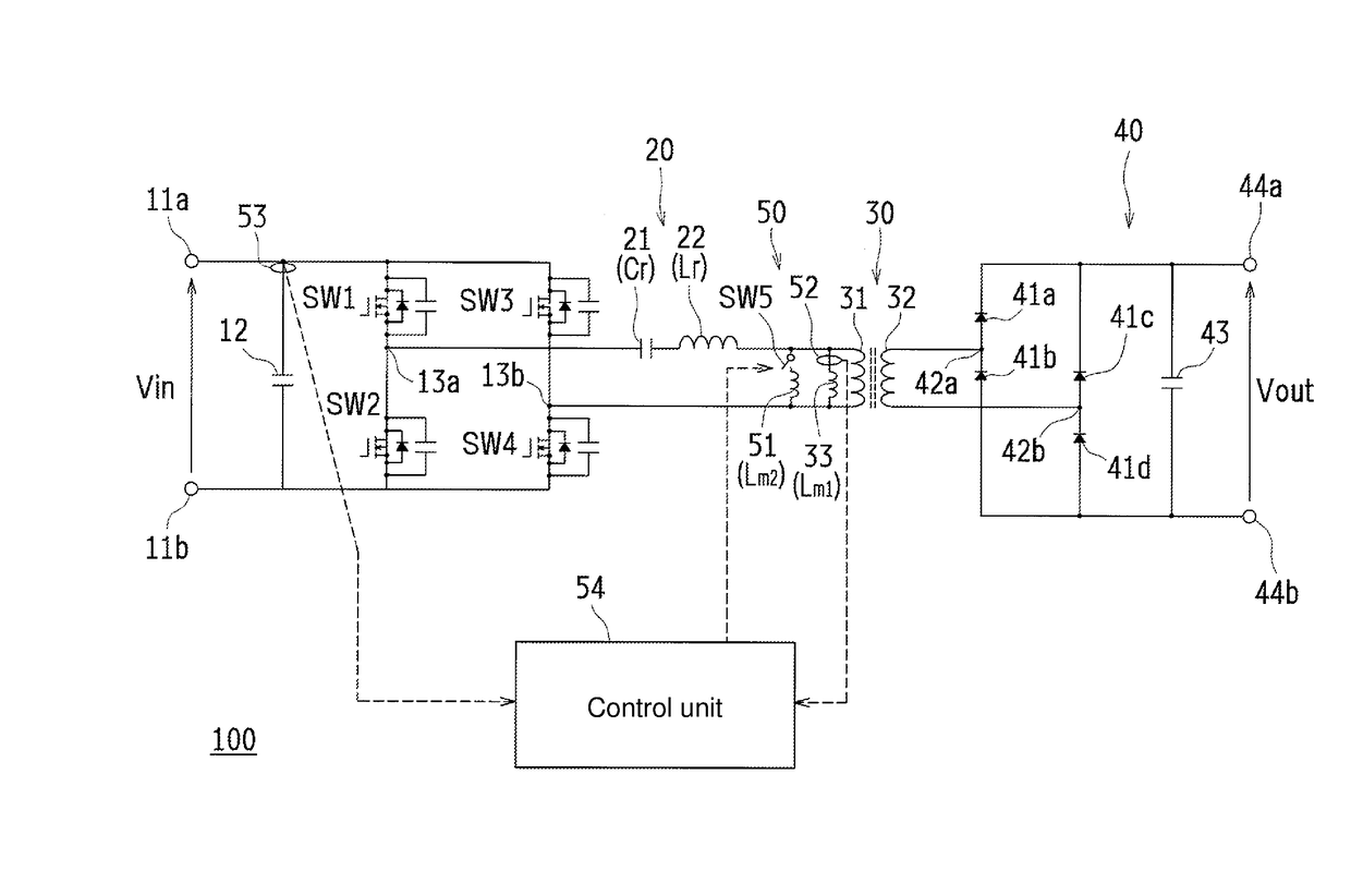
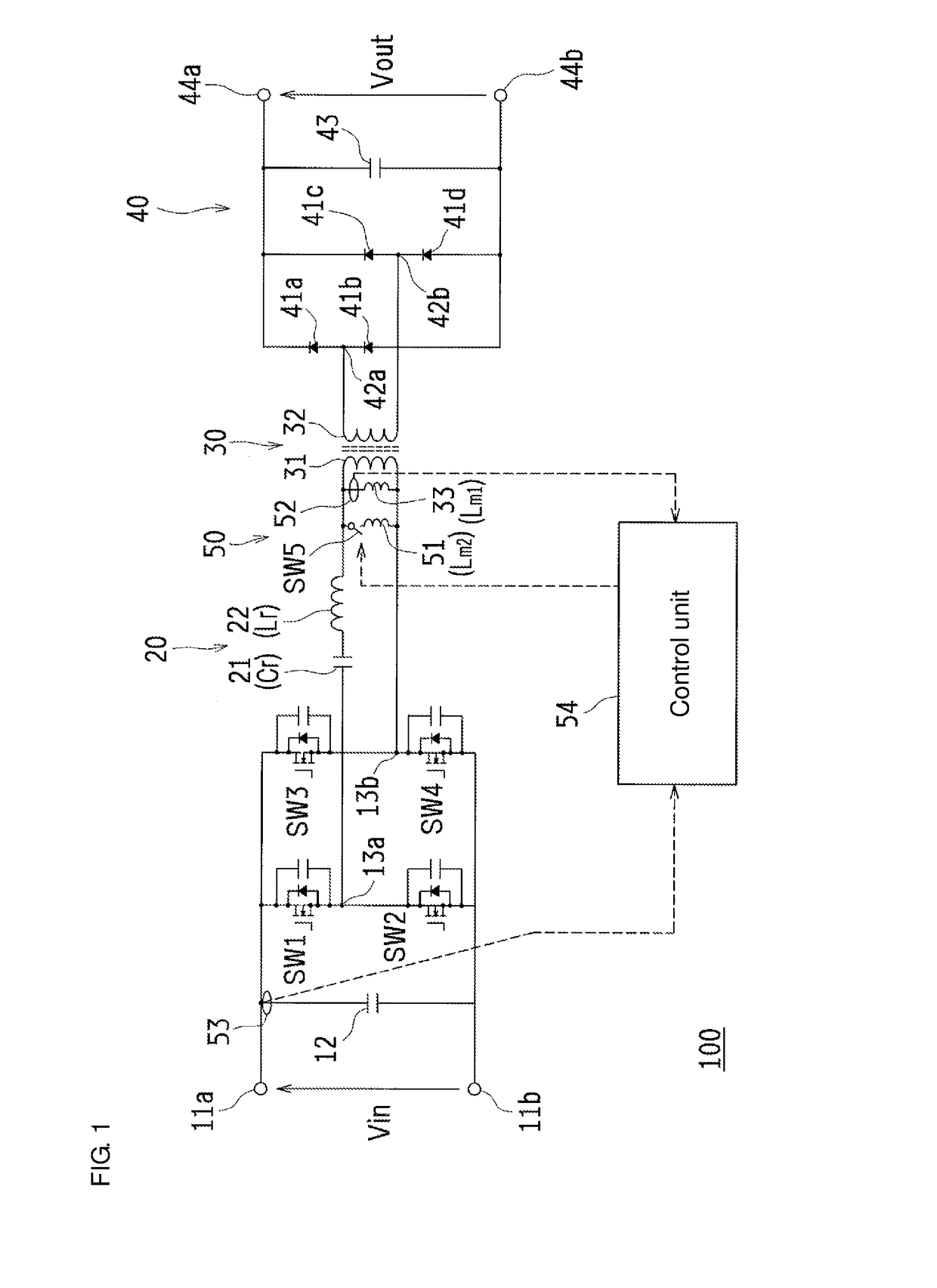
[0093]FIG. 6 is a diagram showing an outline configuration of a parallel resonant inductance adjustment system current resonant type converter 100A according to a first modification example of the first embodiment of the present invention. The same components as those of the first embodiment are identified by the same reference numerals to appropriately omit description thereof.
[0094]Although in the above-described switching circuit 10 of the first embodiment, the switches SW1 to SW4 configure a fullbridge switching circuit, the circuit configuration is not limited thereto. For example, as in the current resonant type converter 100A as illustrated in FIG. 6, the switching circuit 10 of the first embodiment may be replaced by a halfbridge switching circuit 10A and one end of the primary side winding 31 of the transformer 30 (the end not connected to the resonant coil 22 side of the LC resonance circuit 20) may be connected to the input terminal 11b.
second modification example
of the First Embodiment
[0095]FIG. 7 is a diagram showing an outline configuration of a parallel resonant inductance adjustment system current resonant type converter 100B according to a second modification example of the first embodiment of the present invention. The same components as those of the first embodiment are identified by the same reference numerals to appropriately omit description thereof.
[0096]Although in the above-described parallel resonant inductance adjustment circuit 50 of the first embodiment, the current sensor 52 is used which is configured to directly detect a value and a direction of a current passing through the coil 33, a detection method is not limited thereto. For example, as in the current resonant type converter 100B illustrated in FIG. 7, in place of the current sensor 52 of the first embodiment, a current sensor 52a and a current sensor 52b may be provided which are configured to detect a value and a direction of a current passing between the switch S...
second embodiment
[0098]FIG. 8 is a diagram for explaining an outline of on-off control of the switch SW5 in a parallel resonant inductance adjustment system current resonant type converter according to a second embodiment of the present invention.
[0099]In the above-described parallel resonant inductance adjustment circuit 50 of the first embodiment, the control unit 54 conducts control based only on the input voltage Vin detected by the voltage sensor 53 in a manner such that when the input voltage Vin is within the transition condition voltage range, the switch SW5 is tuned off and when the same is not within the transition condition voltage range, the switch SW5 is tuned on.
[0100]However, when the input side is connected to, for example, a solar panel, the input voltage Vin fluctuates according to an amount of solar radiation. When the input voltage Vin minutely fluctuates across an upper limit or a lower limit of the transition condition voltage range, the switch SW5 repeats turning-on and turnin...
PUM
 Abstract
Description
Claims
Application Information
 - R&D
- Intellectual Property
- Life Sciences
- Materials
- Tech Scout
- Unparalleled Data Quality
- Higher Quality Content
- 60% Fewer Hallucinations
Browse by: Latest US Patents, China's latest patents, Technical Efficacy Thesaurus, Application Domain, Technology Topic, Popular Technical Reports.
© 2025 PatSnap. All rights reserved.Legal|Privacy policy|Modern Slavery Act Transparency Statement|Sitemap|About US| Contact US: help@patsnap.com


