Fluid mixer and heat exchange system using same

a technology of mixing device and heat exchange system, which is applied in the direction of indirect heat exchangers, machines/engines, light and heating apparatus, etc., can solve the problem of inability to provide a sufficiently uniform mixing condition, and achieve the effect of suppressing pressure loss and simple structur

Active Publication Date: 2018-10-09
KAWASAKI HEAVY IND LTD
View PDF47 Cites 18 Cited by
  • Summary
  • Abstract
  • Description
  • Claims
  • Application Information

AI Technical Summary

Benefits of technology

[0010]Accordingly, the present invention has been devised to provide a fluid mixing device which is simple in structure, but is capable of accomplishing a uniform mixing accompanied by the pressure loss being suppressed.

Problems solved by technology

It has been found that the fluid mixing device disclosed in the patent document 2 referred to above, although simple in structure, is incapable of providing a sufficiently uniformly mixed condition because the two fluids meet at right angles.

Method used


Image

  • Fluid mixer and heat exchange system using same
  • Fluid mixer and heat exchange system using same
  • Fluid mixer and heat exchange system using same

Examples


Embodiment Construction

[0033]Hereinafter, preferred embodiments of the present invention will be described in detail with reference to the accompany drawings.

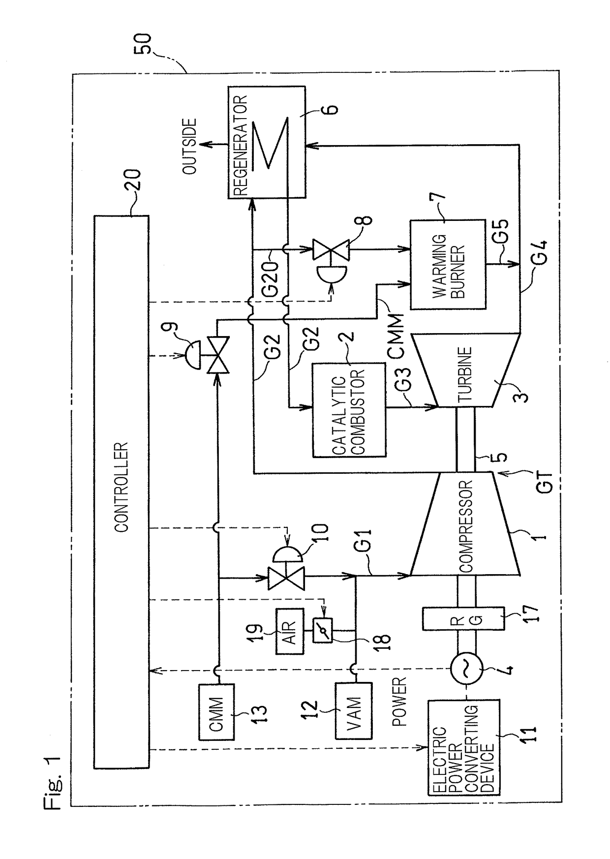
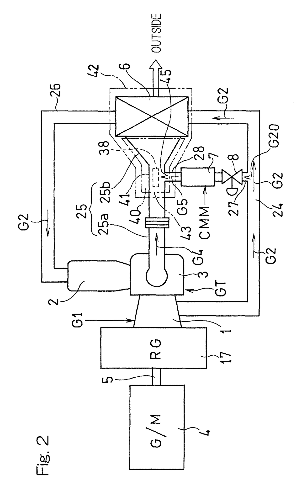
[0034]In particular, FIG. 1 illustrates a schematic structural diagram of a leaned fuel intake type gas turbine system utilizing a fluid mixer designed in accordance with a first preferred embodiment of the present invention. The gas turbine system includes a gas turbine engine GT which in turn includes a compressor 1, a catalytic combustor 2 utilizing a catalyst such as, for example, platinum or palladium, and a turbine 3. By an output of the gas turbine engine GT, a rotating machine 4, which serves as a power generator and a starter, is driven.

[0035]A working gas G1 used in this gas turbine engine GT may be a low calorie gas such as, for example, a VAM (Ventilation Air Methane) medium, produced in a coal mine or a CMM (Coal Mine Methane) medium having a higher concentration of combustible component (methane) than that of the VAM medium, in which ai...


PUM

PropertyMeasurementUnit
angle of inclinationaaaaaaaaaa

Abstract

A fluid mixing device includes a hollow tubular main body (41) to mix an exhaust gas (G4) and a warming gas (G5) within it, a first inflow port (43) provided in an upstream end portion of the main body (41) and through which the exhaust gas (G4) flows, a mixing promotion body (38) of a tubular shape disposed inside the main body (41) and having a longitudinal axis (C1) extending in a direction conforming to a direction of flow of the exhaust gas (G4), and a second inflow port (45) provided in a peripheral wall of the main body (41) and through which the warming gas (G5) flows towards an outer peripheral wall of the mixing promotion body (38). The exhaust gas (G4) flows outside and inside the mixing promotion body (38).

Description

CROSS REFERENCE TO THE RELATED APPLICATION[0001]This application is a continuation application, under 35 U.S.C. § 111(a) of international application No. PCT / JP2012 / 071279, filed Aug. 23, 2012, which claims priority to Japanese patent application No. 2011-223820, filed Oct. 11, 2011, the entire disclosure of which is herein incorporated by reference as a part of this application.BACKGROUND OF THE INVENTION[0002](Field of the Invention)[0003]The present invention relates to a fluid mixing device for uniformly mixing two dissimilar fluids such as, for example, a high temperature fluid and a low temperature fluid.[0004](Description of Related Art)[0005]In an apparatus for mixing a plurality of fluids together, it is desirable that the temperature distribution and the distribution of gas concentrations after the mixing are uniform. For example, where a turbine or a heat exchanger is disposed downstream of the mixing device, unless the temperature distribution of the mixed gas is uniform...

Claims


Application Information

Patent Timeline
Patent Type & Authority Patents(United States)
IPC IPC(8): B01F5/04B01F5/06F02C6/18B01F3/02F02C7/10F28F13/12F28D21/00B01F23/10
CPCB01F5/0403B01F3/02B01F5/0471B01F5/0473B01F5/0659F02C7/10F28D21/001F28F13/125F02C6/18F05D2260/2212F05B2220/60B01F23/10B01F25/3141B01F25/435B01F25/31B01F25/314
Inventor KASHIHARA, HIROYUKIHOSOKAWA, YASUFUMIYAMASAKI, YOSHIHIRO
Owner KAWASAKI HEAVY IND LTD
Why Eureka
Try Eureka