

Tool and method for machining fiber-reinforced materials
a technology of reinforced materials and tools, applied in the direction of turning apparatus, superimposed coating process, chemical vapor deposition coating, etc., can solve the problems of poor surface in the drilled hole, chatter marks in the cone or even the breakage of tools, etc., to increase the overall layer thickness of diamond coating, increase cutting forces and temperatures during machining, and increase the effect of layer strength
- Summary
- Abstract
- Description
- Claims
- Application Information
AI Technical Summary
Benefits of technology
Problems solved by technology
Method used
Image

Examples
examples
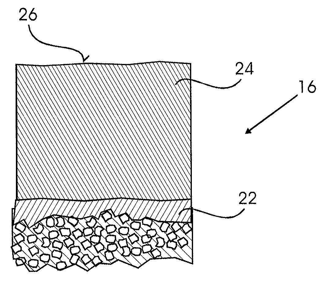
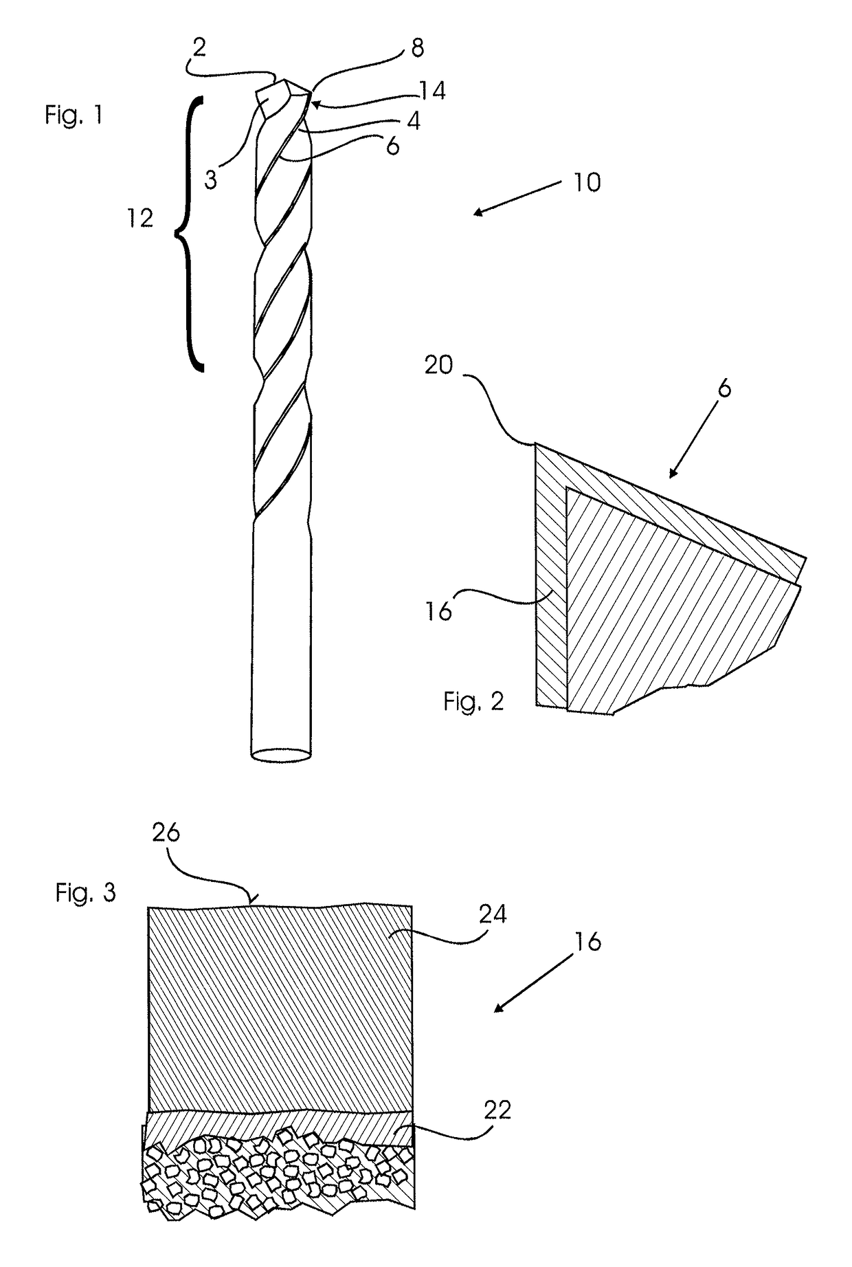
[0064]An 8 mm drill made out of EMT 100 hard metal having 6 wt % Co is first electrochemically etched and 6 μm uniformly removed. Then a particularly gentle chemical pre-treatment is carried out, as described in WO 2004 / 031 437 A1, which reduces the cobalt near the surface and causes a slight roughness. This pre-treatment reduces the diameter of the drill by a further 2 μm. Next, a 0.3 μm-thick crystalline layer is applied by means of the hot-filament process in a coating plant type CC800 / 9 Dia. Finally, the coating parameters are modified in the same process, without vacuum interruption, so that a nanocrystalline layer is applied up to an overall layer thickness of 8 μm by means of a process which commutes between various operating conditions according to WO 2004 / 083 484 A1.
[0065]Produced in this way, the tool shows an increased number of holes compared to conventional, CVD diamond-coated tools, when drilling rivet holes in a CFRP material, the drilling quality being considerably e...
PUM
| Property | Measurement | Unit |
|---|---|---|
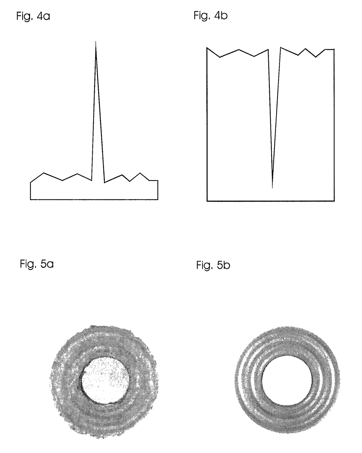
| peak height Spk | aaaaa | aaaaa |
| peak height Spk | aaaaa | aaaaa |
| roughness depth Rz | aaaaa | aaaaa |
Abstract
Description
Claims
Application Information