Method for operation of blast furnace

a blast furnace and blast furnace technology, applied in the field of blast furnace operation, can solve the problems of not being able to fundamentally reduce not having the function to fundamentally cut the amount of co generation, and the features of commercial blast furnaces that pose serious risks, so as to reduce co2 emissions and produce hot metal stably over a long period

Active Publication Date: 2018-10-23
NIPPON STEEL CORP +4
View PDF24 Cites 2 Cited by
  • Summary
  • Abstract
  • Description
  • Claims
  • Application Information

AI Technical Summary

Benefits of technology

[0022]A method for operating a blast furnace to greatly reduce CO2 emissions and to produce hot metal stably over a long period in a commercial blast furnace is provided.

Problems solved by technology

However, none of PLTs 1 to 4 has reduction of CO2 emissions as their main objectives.
They do not sufficiently function to fundamentally cut the amount of generation of CO2.
These features pose serious risks when applied to commercial blast furnaces.
With the current level of art of blast furnace operations which are only demonstrated at a generally 270 kg / tHM or more coke rate, it is not possible to easily create a stable operating state.
In addition, since the oxygen is blown at room temperature, no sensible heat is input by the blown gas.
Therefore, even if trouble occurs in operation causing the furnace to cool, the inside of the furnace cannot be quickly heated and it is difficult to restore operation.
Further, the “closed gas recycling” operation of (2) has the risk of trace elements contained in the gas phase (for example, sulfur content etc.) being recycled and concentrating in the blast furnace process.
In this way, the blast furnace process aimed at by the ULCOS project would be hard to apply to a commercial blast furnace wherein hot metal production is required to be continued stably over a long period of time even if realization were possible on a short time test operation basis.
This method separates and recovers CO2 (and / or CO) from the top gas, adds H2 to this to convert it to CH4, then again blows this into the blast furnace, but there are issues such as the new need for a CH4 conversion apparatus and the fact that if just blowing in CH4, carbon consumption of the blast furnace cannot be sufficiently reduced.

Method used


Image

  • Method for operation of blast furnace
  • Method for operation of blast furnace
  • Method for operation of blast furnace

Examples


example 1

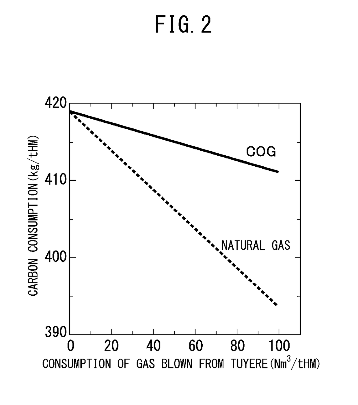
[0043]In Example 1, first, the inventors investigated in detail the above Requirement A “blowing gas containing at least one of hydrogen and a hydrocarbon from a usual tuyere”.

[0044]Table 1 shows the standard parameters at the time of operation of the blast furnace (furnace volume 5300 m3) wherein pulverized coal is injected from the usual tuyere. Consider an operation of blowing CH4-containing gas with a high hydrogen content. If making CH4 rise in temperature to 800° C. or more, it breaks down under the heat whereby hydrogen gas is generated and the hydrogen gas functions as a reducing agent, so the effect of cutting the carbon consumption is obtained.

[0045]The CH4-containing gas contains not only hydrogen, but also a large amount of hydrogen in the state of CH4 or other hydrocarbons, so it is possible to provide it with the function of the reducing material. At this time, the CH4 concentration is preferably 25% or more. The reason is that if the CH4 concentration is less than 25%...

example 2

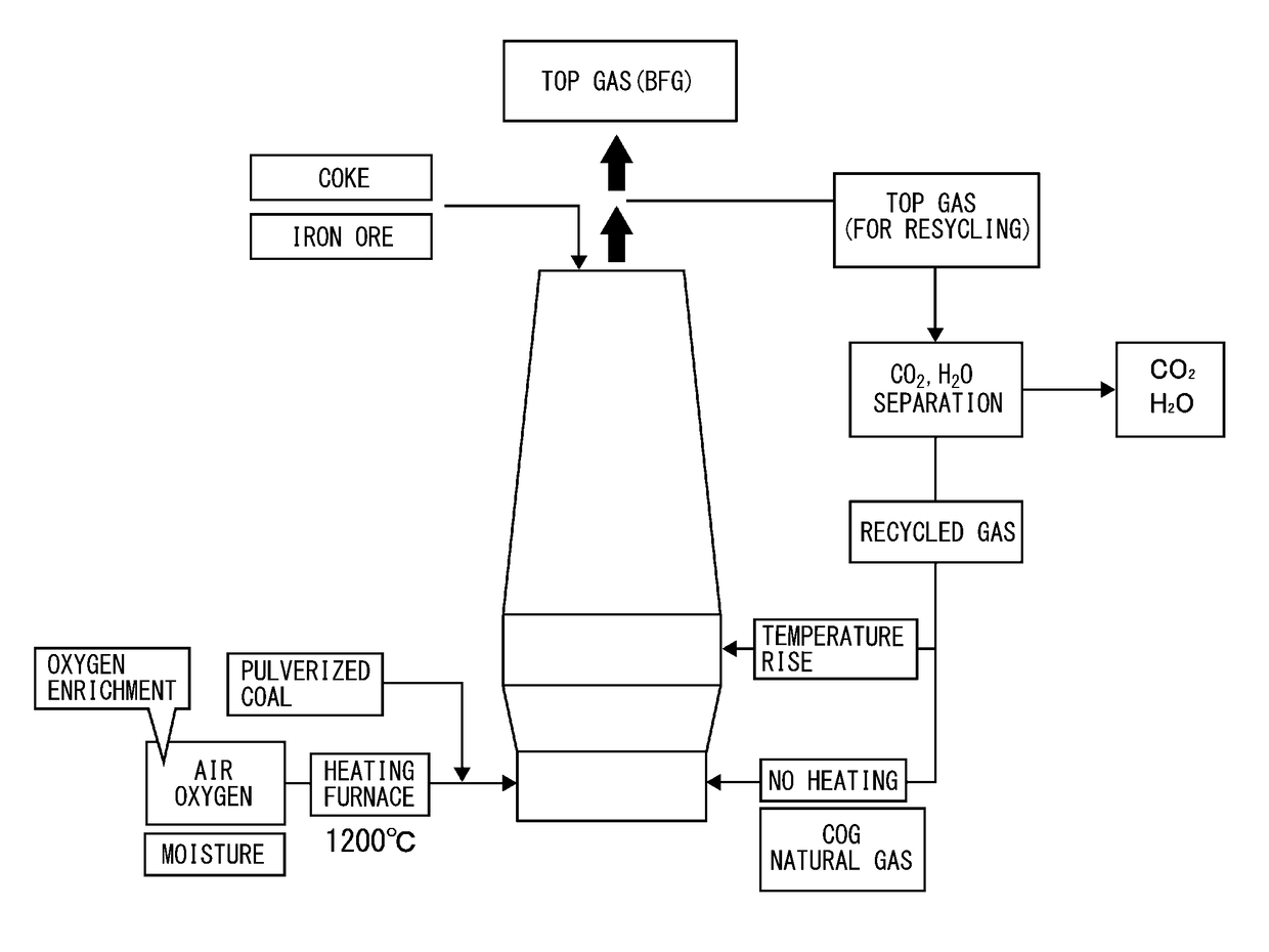
[0067]Next, the inventors studied the operation of a blast furnace further adding to the above (Requirement A+Requirement B) the Requirement C of “blowing top gas from the usual tuyere without heating and increasing the oxygen enrichment of blast”.

[0068]FIG. 6 shows the (Requirement A+Requirement B+Requirement C) process in brief. The Requirement C of the present invention further promotes the reduction of the carbon consumption (kg / tHM) under the (Requirement A+Requirement B). By combining the Requirement C, it is possible to maintain combustion conditions of the tuyere-front combustion location of the blast furnace at a suitable range and reach a coke rate at a level capable of actual operation by existing operating technology.

[0069]As explained above, the upper limit value of the oxygen enrichment is restricted by the presence of erosion of the lance and changes due to the composition of the blast gas. In the case of the present example of only blowing COG containing CH4: 37% fro...

example 3

[0076]FIG. 8 show the relationship among the operation indices of a blast furnace in the case of making natural gas consumption blown from the usual tuyere 95 (Nm3 / tHM) in the (Requirement A+Requirement B+Requirement C) process. Here, the operating conditions in the (Requirement A+Requirement B+Requirement C) process of FIG. 8 are shown in Table 6. Except for the blown gas changing from COG to natural gas, making the blowing rate of recycled gas from the shaft tuyere 400 Nm3 / tHM and making the blowing temperature 800° C., the conditions are the same as the conditions studied in Table 5.

[0077]

TABLE 6Blowing rate of natural gas95 Nm3 / tHM(usual tuyere)Blowing rate of recycled gas400 Nm3 / tHM(shaft tuyere)Blowing rate of recycled gasRate required for(usual tuyere)maintaining flametemperature at 2155° C.Blowing temperature of recycled800° C.gas (shaft tuyere)Blowing temperature of recycledOrdinary temperaturegas (usual tuyere)(25° C.)Oxygen enrichment15 to 40%(usual tuyere)

[0078]FIG. 8A s...


PUM

PropertyMeasurementUnit
temperatureaaaaaaaaaa
grain sizeaaaaaaaaaa

Abstract

A method for operation of a blast furnace able to greatly reduce the CO2 emission and enabling stable production of pig iron over a long period of time in a commercial blast furnace, that is, a method for operation of a blast furnace in which iron ore and coke are charged from a furnace top and is blown in pulverized coal from a usual tuyere, comprising blowing in a gas containing at least one of hydrogen and hydrocarbon from the usual tuyere together with the pulverized coal and blowing a gas comprised of a top gas of the blast furnace from which carbon dioxide and steam is removed from a shaft tuyere into the blast furnace.

Description

TECHNICAL FIELD[0001]The present invention relates to a method for operation of a blast furnace. In particular, it relates to a method for operation of a blast furnace relating to (1) blowing a gas with a high hydrogen content from a usual tuyere, (2) blowing a top gas from the usual tuyere or a tuyere provided at a middle stage of the furnace, and (3) blowing a gas with a high hydrogen content and a top gas from the usual tuyere during which making an oxygen enrichment of the blown gas 10% to 40%.BACKGROUND ART[0002]Production of hot metal in a blast furnace requires a carbonaceous material such as coke, but reduction of the amount of consumption of the carbonaceous material per ton of hot metal (below, called the “reducing agent rate”) is a major objective for reducing manufacturing costs and has been pursued in the past.[0003]For example, PLT 1 has the objective of reducing costs by increasing as much as possible the amount of consumption of small coal which was unable to be used...

Claims


Application Information

Patent Timeline
Patent Type & Authority Patents(United States)
IPC IPC(8): C21B5/06C21B7/00F27B1/10C21B5/00C21B7/16
CPCC21B5/003C21B5/001C21B5/06C21B7/002F27B1/10C21B7/16Y02P10/283C21B2100/282Y02P10/122Y02P10/143Y02P10/25C21B2100/20F27D2019/0031C21B5/00
Inventor INADA, TAKANOBUSAKAI, HIROSHIUJISAWA, YUTAKA
Owner NIPPON STEEL CORP
Why Eureka
Try Eureka