
Methods and systems for central fuel injection

a fuel injection and central fuel technology, applied in the direction of electrical control, machine/engine, exhaust treatment electric control, etc., can solve the problems of affecting the performance of the engine, and being prone to pre-ignition combustion events, etc., to achieve less turbulence, improve pre-ignition mitigation, and generate more particulate matter emissions. or soot

Active Publication Date: 2018-11-06
FORD GLOBAL TECH LLC
View PDF19 Cites 1 Cited by
  • Summary
  • Abstract
  • Description
  • Claims
  • Application Information

AI Technical Summary

Benefits of technology

The patent text describes a method for improving pre-ignition mitigation in engines by selectively increasing the amount of fuel injected via central fuel injection (CFI) while maintaining a stoichiometric air-fuel ratio. This approach reduces the need for cylinder enrichment and increases fuel efficiency while also reducing emissions. The technical effect of this method is improved pre-ignition mitigation without increasing fuel consumption or generating more particulate matter emissions.

Problems solved by technology

Under certain operating conditions, engines that have high compression ratios, or are boosted to increase specific output, may be prone to pre-ignition combustion events.
The early combustion due to pre-ignition can cause very high in-cylinder pressures, and can result in combustion pressure waves similar to combustion knock, but with larger intensity that may damage engine components.
However the inventors herein have recognized potential issues with such an approach.
As one example, while the charge cooling effect of the direct injection improves pre-ignition mitigation, it also generates more particulate matter emissions (or soot) due to diffuse flame propagation wherein fuel may not adequately mix with air prior to combustion.
Since direct injection, by nature, is a relatively late fuel injection, there may be insufficient time for mixing of the injected fuel with air in the cylinder.
Consequently, there may be pockets of richer than stoichiometric combustion that may generate soot locally, degrading exhaust emissions.
In addition, the enrichment can lead to increased fuel consumption.
Further, if multiple cylinders are affected by pre-ignition concurrently, and each cylinder is enriched, fuel consumption may increase significantly.

Method used


Image

  • Methods and systems for central fuel injection
  • Methods and systems for central fuel injection
  • Methods and systems for central fuel injection

Examples


Embodiment Construction

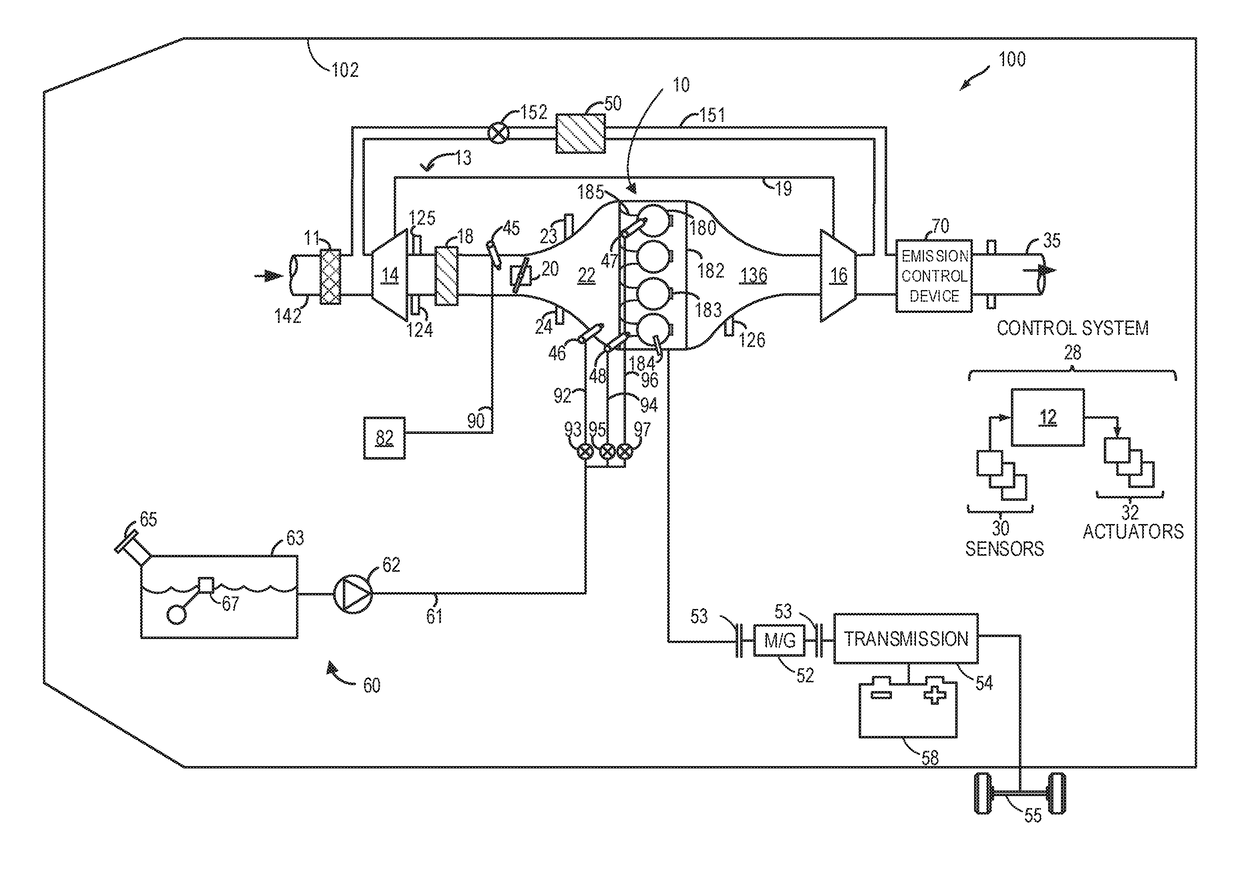
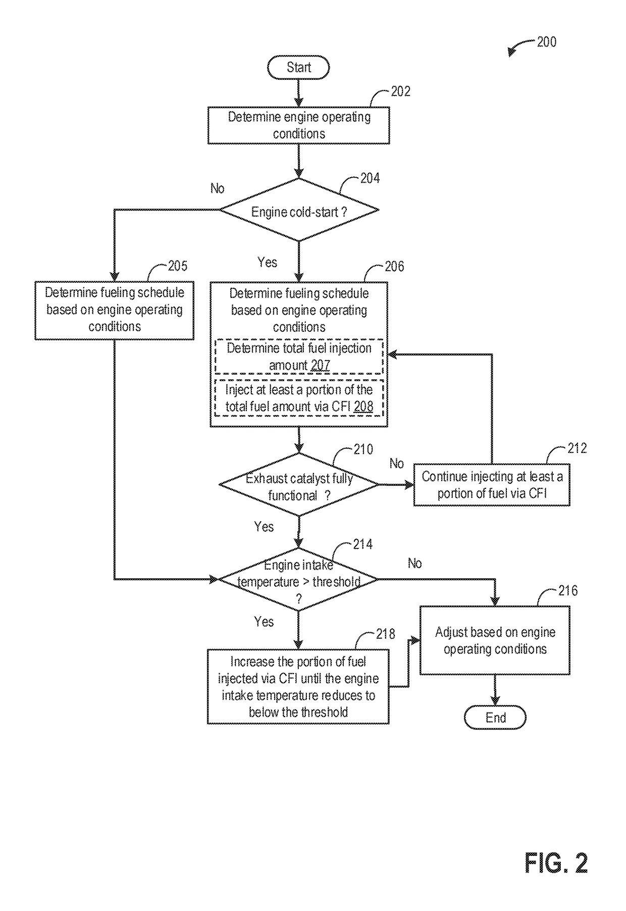
[0017]The following description relates to systems and methods for leveraging manifold fuel injection for increased charge air cooling, for reduced NOx emissions, and for pre-ignition mitigation. The methods herein may be applied to an engine system having manifold, direct, and port fuel injection capabilities, such as the engine system of FIG. 1. An engine controller may be configured to perform a control routine, such as the example routines of FIGS. 2, 3, and 5, to adjust a fueling schedule, including adjusting an amount of fuel delivered via manifold injection relative to the amount of fuel delivered via port injection and / or direct injection for reduction of NOx production and for pre-ignition mitigation. Example adjustments of fueling schedule for attaining a desired charge cooling for NOx reduction and pre-ignition mitigation are shown at FIGS. 4 and 8. Examples of fuel split ratios between manifold injection and port injection (and / or direct injection) are shown in FIGS. 6 a...


PUM


Abstract

Methods and systems are provided for adjusting engine operating conditions for mitigation of pre-ignition in one or more engine cylinder. In one example, a method may include, in response to indication of pre-ignition, manifold charge cooling may be increased by increasing the portion of fuel delivered to the engine via manifold injection relative to the portion to fuel delivered via one or more of port and direct injection, while maintaining engine operation at or around a stoichiometric air-fuel ratio.

Description

FIELD[0001]The present description relates generally to methods and systems for controlling a vehicle engine in response to pre-ignition detection.BACKGROUND / SUMMARY[0002]Under certain operating conditions, engines that have high compression ratios, or are boosted to increase specific output, may be prone to pre-ignition combustion events. The early combustion due to pre-ignition can cause very high in-cylinder pressures, and can result in combustion pressure waves similar to combustion knock, but with larger intensity that may damage engine components. Strategies have been developed for prediction and / or early detection of pre-ignition based on engine operating conditions.[0003]Various approaches may be provided for mitigating pre-ignition. In one approach, as shown by Glugla et al. in US 20120245827, in response to an indication of pre-ignition, a pre-ignition affected cylinder is enriched via multiple intake and / or compression stroke direct injections instead of a single direct i...

Claims


Application Information

Patent Timeline
Patent Type & Authority Patents(United States)
IPC IPC(8): F01N3/02F01N3/20F01N3/10F02D41/30F02D41/40F02D35/02F02D41/02F01N9/00F02M69/04F01N3/021F02D41/14G01M15/11G01M15/12
CPCF02D41/3094F02D41/1498F02D41/029F02D35/027F02D35/028F02M69/046F01N9/002F02D41/402F01N3/021F02M69/045F02M69/044F02D41/403F02D2200/025G01M15/11G01M15/12F02D41/1454F02D41/40F02D41/0255F02D41/0295F02D41/1475F02D2200/0414F02D2200/0812F01N2430/06F01N2900/1624F02M69/043
Inventor SURNILLA, GOPICHANDRARANGA, ADITHYA PRAVARUN REHAKEEM, MOHANNADULREY, JOSEPH NORMANTRESCOTT, CALVIN
Owner FORD GLOBAL TECH LLC
Learn More