Sealed secondary battery

a secondary battery and seal technology, applied in the direction of batteries, cell components, cell component details, etc., can solve problems such as deformation of the case, and achieve the effect of quick disconnecting the conduction path

Active Publication Date: 2018-11-13
TOYOTA JIDOSHA KK
View PDF26 Cites 0 Cited by
  • Summary
  • Abstract
  • Description
  • Claims
  • Application Information

AI Technical Summary

Benefits of technology

[0011]The present invention has been made in view of such circumstances, with an objective thereof being to provide a sealed secondary battery such that its current-blocking system yields little change in the actuation pressure even on long-term use.

Problems solved by technology

Upon such overcharge, the battery reactions proceed rapidly, gas is produced inside the sealed battery case to increase the internal pressure (gas pressure) of the battery case, and the abnormal internal pressure may cause deformation of the case, etc.

Method used


Image

  • Sealed secondary battery
  • Sealed secondary battery
  • Sealed secondary battery

Examples


example 1

[0119]Current-blocking system 180 having a constitution shown in FIG. 6 and FIG. 7 were installed in cylindrical main casings 114 to construct test samples A1 to A5. As the pressure-sensitive member 130, species having the shapes indicated in Table 1 were fabricated and used, respectively. For instance, using an aluminum sheet (A1050) having a thickness b of 0.3 mm, the pressure-sensitive member 130 for Sample A1 was fabricated by stamping out a circle from the aluminum sheet and press-molding it into the shape indicated in Table 1. In the pressure-sensitive member 130 for Sample A1, the outer diameter a of flange 134 was 30 mm while the outer diameter d of pressure-sensitive deformable portion 132 was 16 mm. Thus, the width of flange 134 was 7 mm. The depth c of the concavity formed by pressure-sensitive deformable portion 132 was 1.2 mm. The curved portion 132B was in a ball shell shape having a curvature radius e of 10.5 mm. At the central portion of pressure-sensitive deformable...

example 2

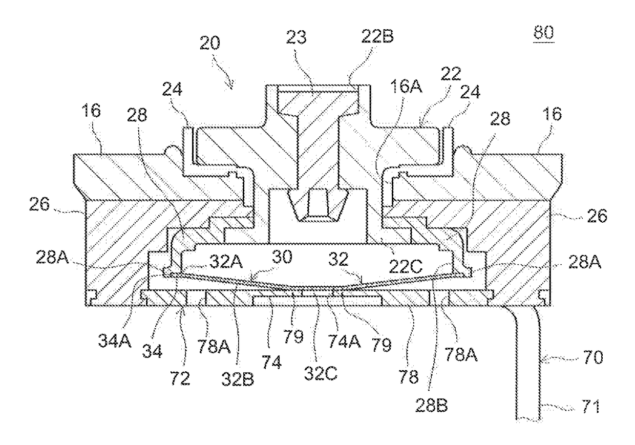
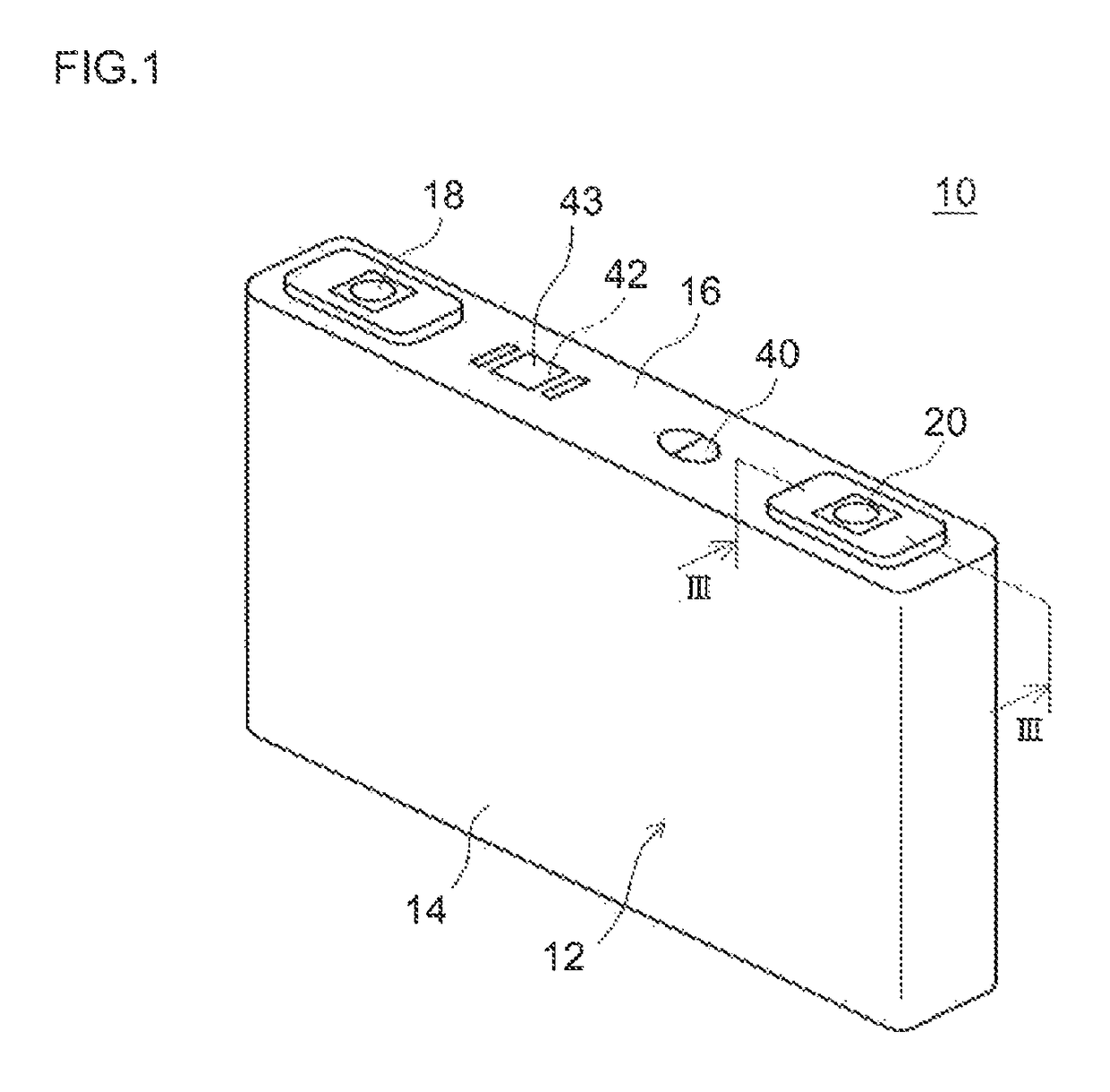
[0125]Current-blocking systems 80 having a constitution shown in FIG. 3 were installed in square battery cases 12 shown in FIG. 1 to construct test Samples B1 to B8. As the pressure-sensitive members 30, were used those having the respective values of ratios (b / a), (c / a), (d / a) and tan θ shown in Table 2, respectively. For each of Samples B1 to B8, the value of a was in a range of 14 mm to 20 mm while b was in a range of 0.2 mm to 0.5 mm.

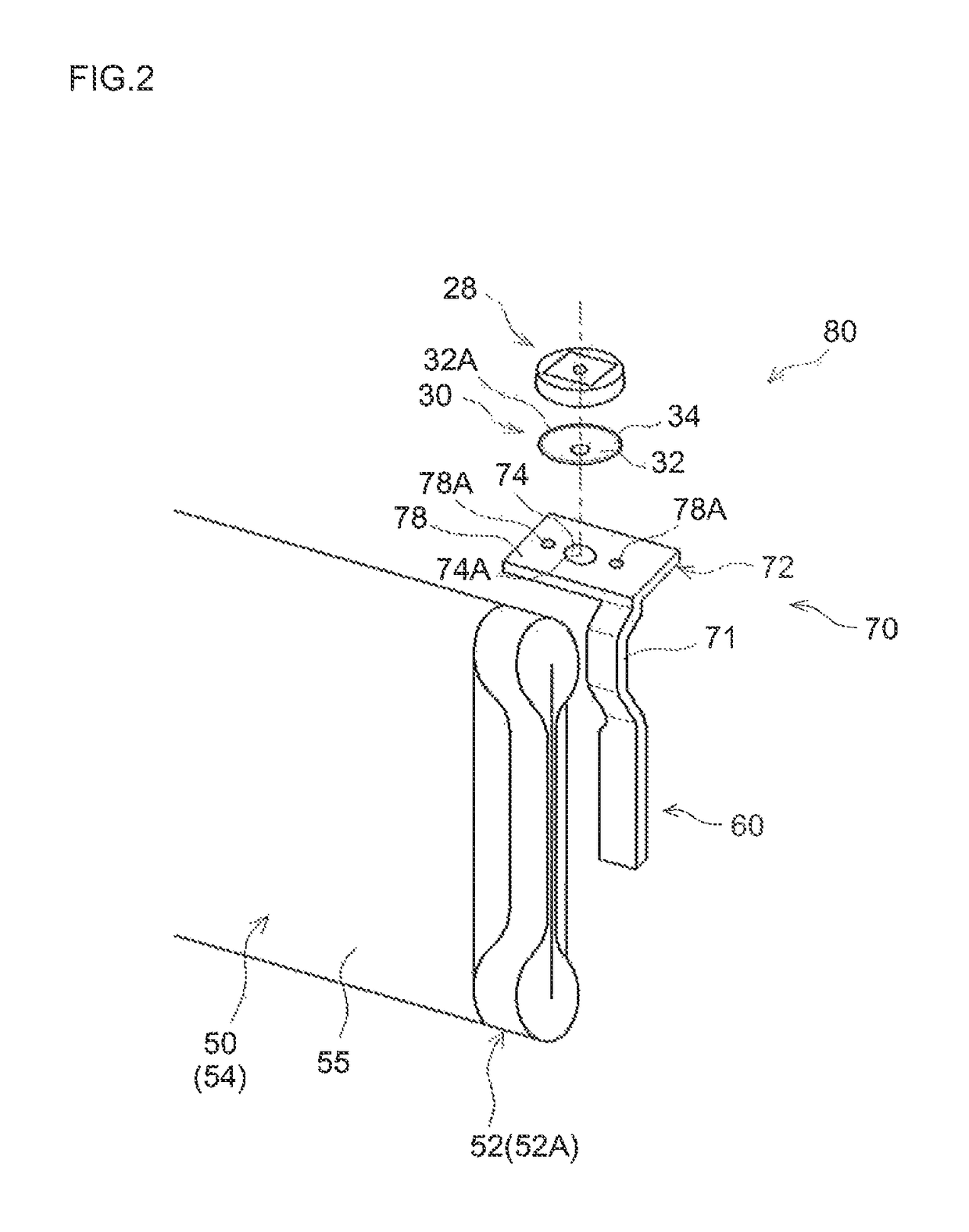
[0126]With respect to each of a total of eight different pressure-sensitive members 30 thus fabricated, flange 34 was fastened on the end portion 28A of pressure-sensitive member holder 28 while the flat portion 32C of pressure-sensitive deformable portion 32 was welded by laser to the thin portion 74 of current collector plate 72 on the inner side (inner diameter side) relative to the position of groove 79. These members were mounted on a sealing plate 16, and the seam between the sealing plate 16 and main casing 14 was welded by laser. This hermet...

example 3

[0129]By adjusting the depth of groove 179 formed in the thin portion 174 of conductive plate 172 in the current-blocking system according to Sample A2, a conductive plate having a remaining thickness larger by 5 μm than the remaining thickness β (μm) of the conductive plate used in Sample A2 (i.e. a conductive plate having a remaining thickness of β+5 μm, i.e., having a depth of groove 179 smaller by 5 μm than that of the conductive plate of Sample A2), a conductive plate having a remaining thickness larger by 10 μm (remaining thickness of β+10 μm), and a conductive plate having a remaining thickness larger by 15 μm (remaining thickness β+15 μm) were fabricated. In the same manner as Example 1 except that these conductive plates were used, test samples were fabricated. In the same manner as Example 1, air was supplied into the case of each test sample to increase the internal pressure of the case. Additionally, when the conduction between pressure-sensitive member 130 and conductiv...


PUM

PropertyMeasurementUnit
depthaaaaaaaaaa
curvature radiusaaaaaaaaaa
thicknessaaaaaaaaaa

Abstract

There is provided a sealed secondary battery whose current-blocking system yields little change in the actuation pressure even on long-term use. The sealed secondary battery comprises a current-blocking system 80 that is actuated by a pressure rise inside a battery case 12 to disconnect conduction path between an electrode and an electrode terminal. Current-blocking system 80 comprises a pressure-sensitive member having a pressure-sensitive deformable portion 32 that deforms from a first state via snap-through deformation to a second state upon a pressure rise inside battery case 12, and is configured to disconnect the conduction path by snap-through deformation of pressure-sensitive deformable portion 30.

Description

CROSS-REFERENCE TO RELATED APPLICATIONS[0001]This application is a national phase application of International Application No. PCT / JP2012 / 061618, filed May 2, 2012, the content of which is incorporated herein by reference.TECHNICAL FIELD[0002]The present invention relates to a sealed secondary battery. In particular, it relates to a sealed secondary battery comprising a current-blocking system actuated by an increase in the internal pressure.BACKGROUND ART[0003]Secondary batteries such as lithium secondary batteries and nickel-hydrogen batteries are preferably used as so-called portable power supplies in personal computers, mobile devices, etc., or as vehicle-driving power supplies. In particular, lithium secondary batteries that are lightweight and have high energy densities have become increasingly important as high output power supplies for use on vehicles such as electric automobiles, hybrid mobiles and the like (e.g. as power sources to drive motors connected to drive wheels of...

Claims


Application Information

Patent Timeline
Patent Type & Authority Patents(United States)
IPC IPC(8): H01M2/34H01M2/22H01M10/34H01M50/528
CPCH01M2/345H01M2/22H01M10/34H01M2220/20H01M2200/20H01M50/528H01M50/578Y02E60/10H01M50/10
Inventor KOBAYASHI, KEIICHIROFUKUSHI, TAKANORI
Owner TOYOTA JIDOSHA KK
Why Eureka
Try Eureka