System and method for refueling a compressed gas pressure vessel using a thermally coupled nozzle

a technology of compressed gas and thermal coupling, which is applied in the direction of gas/liquid distribution and storage, vessel construction details, road vehicles, etc., can solve the problems of high cost of lng, large and cumbersome fuel tanks, and use of natural gas in vehicles

Active Publication Date: 2018-11-20
MOSAIC TECH DEV
View PDF10 Cites 5 Cited by
  • Summary
  • Abstract
  • Description
  • Claims
  • Application Information

AI Technical Summary

Benefits of technology

[0014]It is an object of some embodiments of the present invention to provide consumers with improvements and advantages over the above described prior art, and / or overcome and alleviate one or, more of the above described disadvantages of the prior art, and / or provide a useful commercial choice.

Problems solved by technology

A key factor limiting the use of natural gas in vehicles is the storage of the natural gas fuel.
In the case of CNG and LNG, the fuel tanks are generally expensive, large and cumbersome relative to tanks required for conventional liquid fuels having equivalent energy content.
In addition, the relative lack of wide availability of CNG and LNG refuelling facilities, and the cost of LNG, add further limitations on the use of natural gas as a motor vehicle fuel.
Further, in the case of LNG, the cost and complexity of producing LNG and issues associated with storing a cryogenic liquid on a vehicle further limit the widespread adoption of this fuel.
While LNG has had some success as a liquid fuel replacement in some regions of the world, the lack of availability of LNG and its high cost means that in many regions of the world it is not a feasible alternative fuel.
However, cost versus benefit comparisons are often not favourable in the case of private motor cars.
Issues associated with the size and shape of the fuel tank, the cost variability of LPG and the sometimes limited supply mean that LPG also has significant disadvantages that limit its widespread adoption.
However, some technical problems still limit the efficiency of CNG fuel systems.
For example, the pressure to which composite CNG cylinders can be filled at a typical CNG re-fuelling station is limited because the heat of compression can cause overheating of cylinders being filled.
This has a significant detrimental impact on the range of CNG vehicles, and also on consumers who often have difficulty understanding the variability of a CNG cylinder fill and the impacts on vehicle range.
Also, the variability and inability to fully fill CNG cylinders has a major impact on the use of CNG cylinders in bulk gas transport, where poor CNG cylinder filling has significant commercial impact on the cost of gas delivered.
These limitations meant that the currently available composite cylinders designed for 350 barg operating pressure and above could not be utilised in conventional CNG re-fuelling systems.
Thus the opportunity to utilise smaller CNG cylinders, or to achieve increases in vehicle range, or improved commercial outcomes for gas transport, using the same size fuel cylinders, can not be realised.
A further problem with current systems for fast refuelling of large CNG vessels, such as used in buses and trucks, is that the size and weight of the refuelling connection makes them difficult to handle and problematic relative to the smaller connectors used commonly for filling cars.
However, with this system the delivery of liquid into and out of CNG cylinders limits the application of the technology, and can slow transfer rates due to limitations in the liquid handling.

Method used


Image

  • System and method for refueling a compressed gas pressure vessel using a thermally coupled nozzle
  • System and method for refueling a compressed gas pressure vessel using a thermally coupled nozzle
  • System and method for refueling a compressed gas pressure vessel using a thermally coupled nozzle

Examples


Embodiment Construction

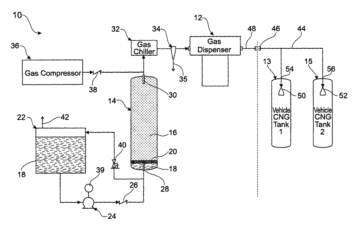
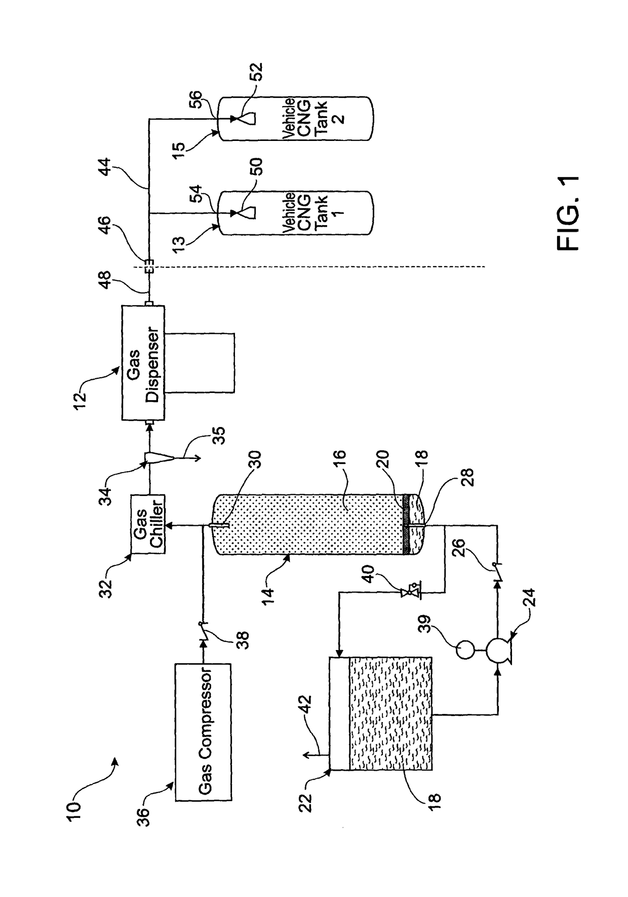
[0037]Embodiments of the present invention comprise systems and methods for refuelling compressed gas pressure vessels using a thermally coupled nozzle. Elements of the invention are illustrated in concise outline form in the drawings, showing only those specific details that are necessary to the understanding of the embodiments of the present invention, but so as not to clutter the disclosure with excessive detail that will be obvious to those of ordinary skill in the art in light of the present description.

[0038]In this patent specification, adjectives such as first and second, left and right, front and back, top and bottom, etc., are used solely to define one element or method step from another element or method step without necessarily requiring a specific relative position or sequence that is described by the adjectives. Words such as “comprises” or “includes” are not used to define an exclusive set of elements or method steps. Rather, such words merely define a minimum set of ...


PUM


Abstract

A pressure vessel refueling system enables consistent mass flow rates and reduces the in-tank temperature rise caused by the heat of compression as gas is added to a vessel. The system includes a pressure vessel having a first gas inlet / outlet port and an interior cavity, and a nozzle is in fluid communication with the first gas inlet / outlet port. The nozzle and the pressure vessel are thermally coupled such that Joule-Thomson expansion of a gas flowing through the nozzle cools the interior cavity and contents of the pressure vessel.

Description

FIELD OF THE INVENTION[0001]This invention relates generally to a compressed gas transfer system. In particular, the invention relates to a compressed natural gas (CNG) transfer system including a nozzle thermally coupled to and optionally inside a CNG cylinder to reduce temperature rises in the cylinder.BACKGROUND OF THE INVENTION[0002]Natural gas fuels are relatively environmentally friendly for use in vehicles, and hence there is support by environmental groups and governments for the use of natural gas fuels in vehicle applications. Natural gas based fuels are commonly found in three forms: Compressed Natural Gas (CNG), Liquefied Natural Gas (LNG) and a derivative of natural gas called Liquefied Petroleum Gas (LPG).[0003]Natural gas fuelled vehicles have impressive environmental credentials as they generally emit very low levels of SO2 (sulphur dioxide), soot and other particulate matter. Compared to gasoline and diesel powered vehicles, CO2 (carbon dioxide) emissions of natural...

Claims


Application Information

Patent Timeline
Patent Type & Authority Patents(United States)
IPC IPC(8): F17C5/06F17C5/00
CPCF17C5/007F17C5/06F17C2201/032F17C2201/054F17C2205/035F17C2205/0341F17C2205/0367F17C2205/0391F17C2221/033F17C2223/0123F17C2223/033F17C2225/0123F17C2225/036F17C2225/043F17C2227/0192F17C2227/036F17C2227/0337F17C2227/0372F17C2227/0388F17C2250/01F17C2260/023F17C2265/065F17C2270/0139F17C2270/0171F17C2270/0176F17C2270/0178F17C2201/0109
Inventor WHITEMAN, PAUL ANTHONYFEKETE, DEREK SHANE
Owner MOSAIC TECH DEV
Why Eureka
Try Eureka