
Battery pack

a battery pack and battery technology, applied in the field of batteries, can solve the problems of large capacity loss (impact of decreased volume energy density), large thickness of the casing, and high cost, and achieve the effect of preventing overheating and effectively preventing overheating

Active Publication Date: 2018-11-20
TOYOTA JIDOSHA KK
View PDF15 Cites 0 Cited by
  • Summary
  • Abstract
  • Description
  • Claims
  • Application Information

AI Technical Summary

Benefits of technology

The invention aims to improve secondary batteries that have a casing with a given electrical potential. The objective is to reduce heat buildup and increase battery capacity in the event of damage. The invention provides a battery pack that comprises multiple single batteries with casings that have given electrical potentials. This helps prevent concentration of short-circuit current and overheating inside the battery, while also increasing battery capacity. The casing requires a thicker thickness to bear the short-circuit current, which can lead to a significant capacity loss. The invention addresses this issue by reducing the impact of the casing thickness and increasing battery capacity while reducing heat buildup.

Problems solved by technology

When a secondary battery such as a lithium-ion secondary battery is pierced with a sharp metal piece in the event of damage such as crushing, via the metal piece stuck in the electrode body inside the battery, etc., a short circuit may occur between the positive and negative electrodes within the electrode body, thereby causing a heat buildup.
With this configuration, however, the casing requires a large enough thickness to bear the short-circuit current.
Thus, in a battery pack in which the secondary batteries are arrayed as single batteries, because of the larger thickness of the casing, the capacity loss (impact of the decreased volume energy density) becomes significant.
This leads to further thinning.

Method used


Image

  • Battery pack
  • Battery pack
  • Battery pack

Examples


examples

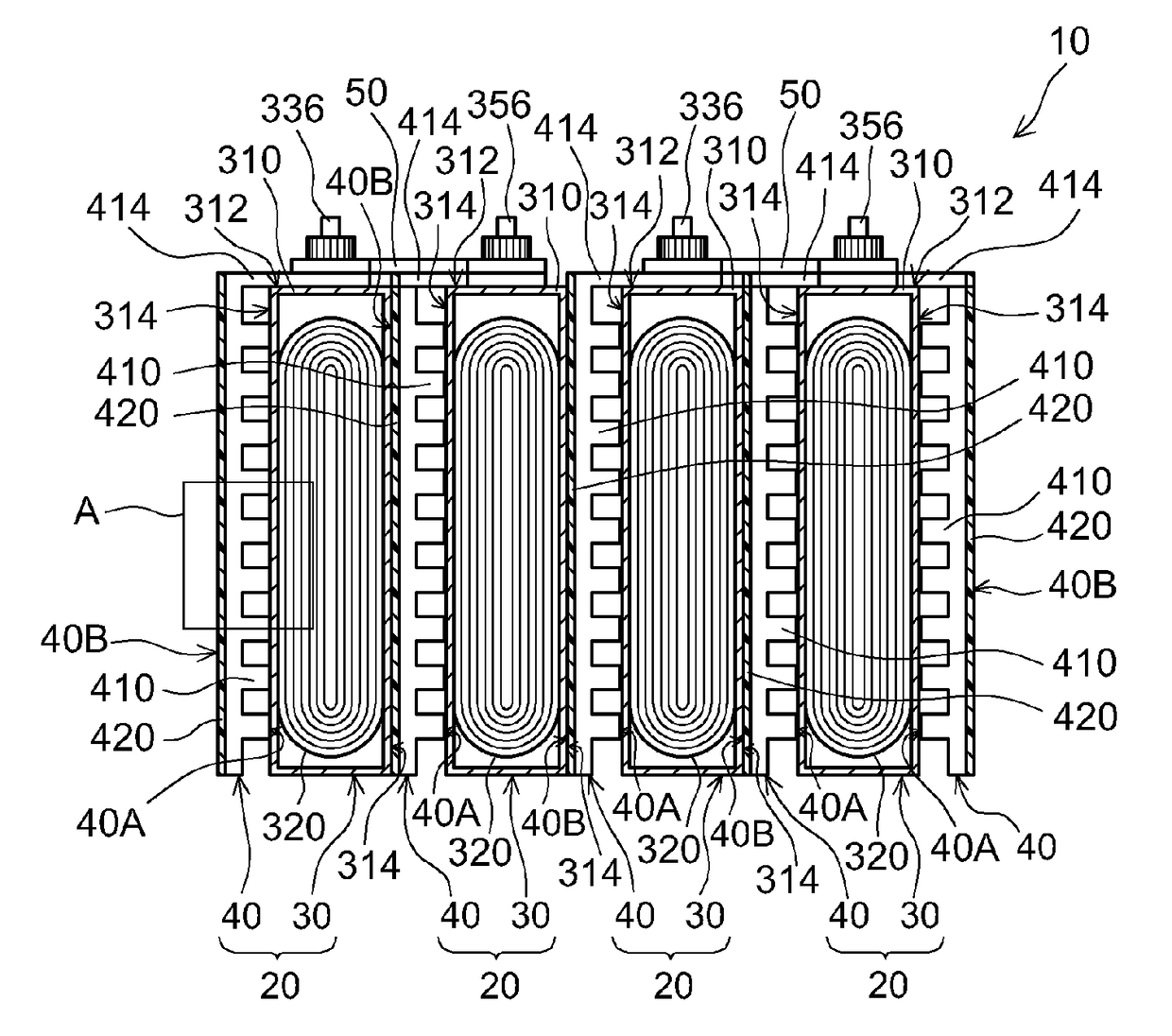
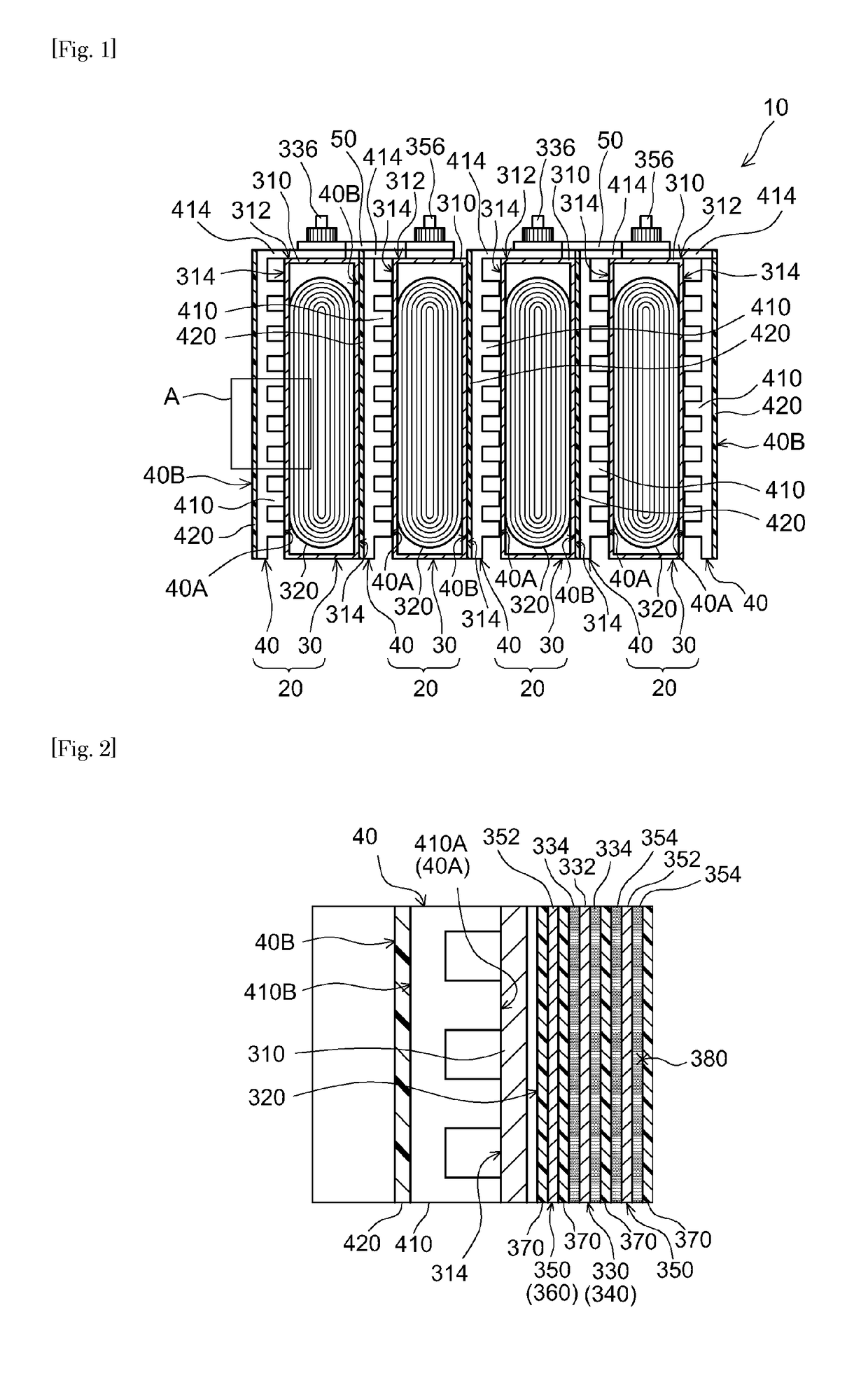
[0054]Verification tests related to the present invention are discussed next. As test batteries, power-generating elements 1 to 5 (battery capacity: 35 Ah) having square lithium-ion secondary batteries and protection plates (cooling plates) were constructed. Power-generating elements 2 to 5 have basically the same configuration as the power-generating element according to the embodiment described above (a configuration as shown in FIGS. 1 and 2); and the thicknesses of the casings and metal layers are as shown in Table 1. Power-generating element 1 has a conventional configuration without a metal layer and a 6.0 mm thick resin plate is used as the cooling plate corresponding to the protection plate. Otherwise, it has the same configuration as power-generating elements 2 to 5.

[Needle Penetration Test]

[0055]Each power-generating element obtained was subjected to a prescribed conditioning treatment. Subsequently, the voltage across the positive and negative electrodes was adjusted to 4...


PUM

PropertyMeasurementUnit
thicknessaaaaaaaaaa
thicknessaaaaaaaaaa
thicknessaaaaaaaaaa

Abstract

Provided is a battery pack with the heat buildup associated with battery damage can be reduced while increasing the battery capacity. This invention provides a battery pack having an array of power-generating elements comprising rechargeable single batteries. Each single battery comprises a casing and an electrode body in the casing. In the electrode body, the outermost circumference of the negative electrode is outside the outermost circumference of the positive electrode. The power-generating element further comprises a protection plate placed along the outer surface of the single battery. The protection plate has a metal layer and an insulating layer. The metal layer has first and second surfaces on the single battery side and on the side opposite from the first surface, respectively. The insulating layer is placed on the second surface side of the metal layer. The metal layer is electrically connected to the positive electrode with a given positive potential.

Description

CROSS-REFERENCE[0001]The present application claims priority to Japanese Patent Application No. 2015-120578 filed on Jun. 15, 2015; and the entire contents thereof are incorporated herein by reference.BACKGROUND OF THE INVENTION[0002]1. Field of the Invention[0003]The present invention relates to a battery pack.[0004]2. Description of the Related Art[0005]Lightweight yet high-energy density lithium-ion secondary batteries, nickel-hydrogen secondary batteries and other secondary batteries are widely used as power supplies for vehicles, PCs, mobile terminals and so on. In particular, battery packs of the secondary batteries serving as single batteries (battery cells) that are connected together are preferably used as high power batteries for vehicles such as electric automobiles and hybrid automobiles. In general, a secondary battery as described above is constructed to have an electrode body in a casing, with the electrode body comprising positive and negative electrodes with a separ...

Claims


Application Information

Patent Timeline
Patent Type & Authority Patents(United States)
IPC IPC(8): H01M2/10H01M2/02H01M10/04H01M10/0525H01M10/0587B60L50/64
CPCH01M2/1077H01M2/027H01M10/0431H01M2/1094H01M10/0587H01M10/0525H01M10/613H01M10/625H01M10/6554H01M10/42H01M2220/20H01M50/224B60L50/64H01M50/249H01M50/213Y02E60/10H01M50/545H01M50/24Y02P70/50Y02T10/70H01M50/20H01M50/209
Inventor KATO, MASAKI
Owner TOYOTA JIDOSHA KK
Learn More