Magnetic field measurement device

a magnetic field and measurement device technology, applied in the direction of instruments, lasers, material analysis, etc., can solve the problem that the light intensities of light sources including semiconductor lasers are typically not always stable, and achieve the effect of stable operation and low nois

Active Publication Date: 2018-12-25
HITACHI LTD
View PDF61 Cites 7 Cited by
  • Summary
  • Abstract
  • Description
  • Claims
  • Application Information

AI Technical Summary

Benefits of technology

[0017]The present invention provides lower noise and stable operation of an optically pumped magnetic sensor with a device configuration capable of achieving both of intensity stabilization of a light source and frequency stabilization thereof.

Problems solved by technology

The light intensities of light sources including semiconductor lasers are typically not always stable.

Method used


Image

  • Magnetic field measurement device
  • Magnetic field measurement device
  • Magnetic field measurement device

Examples


embodiment 1

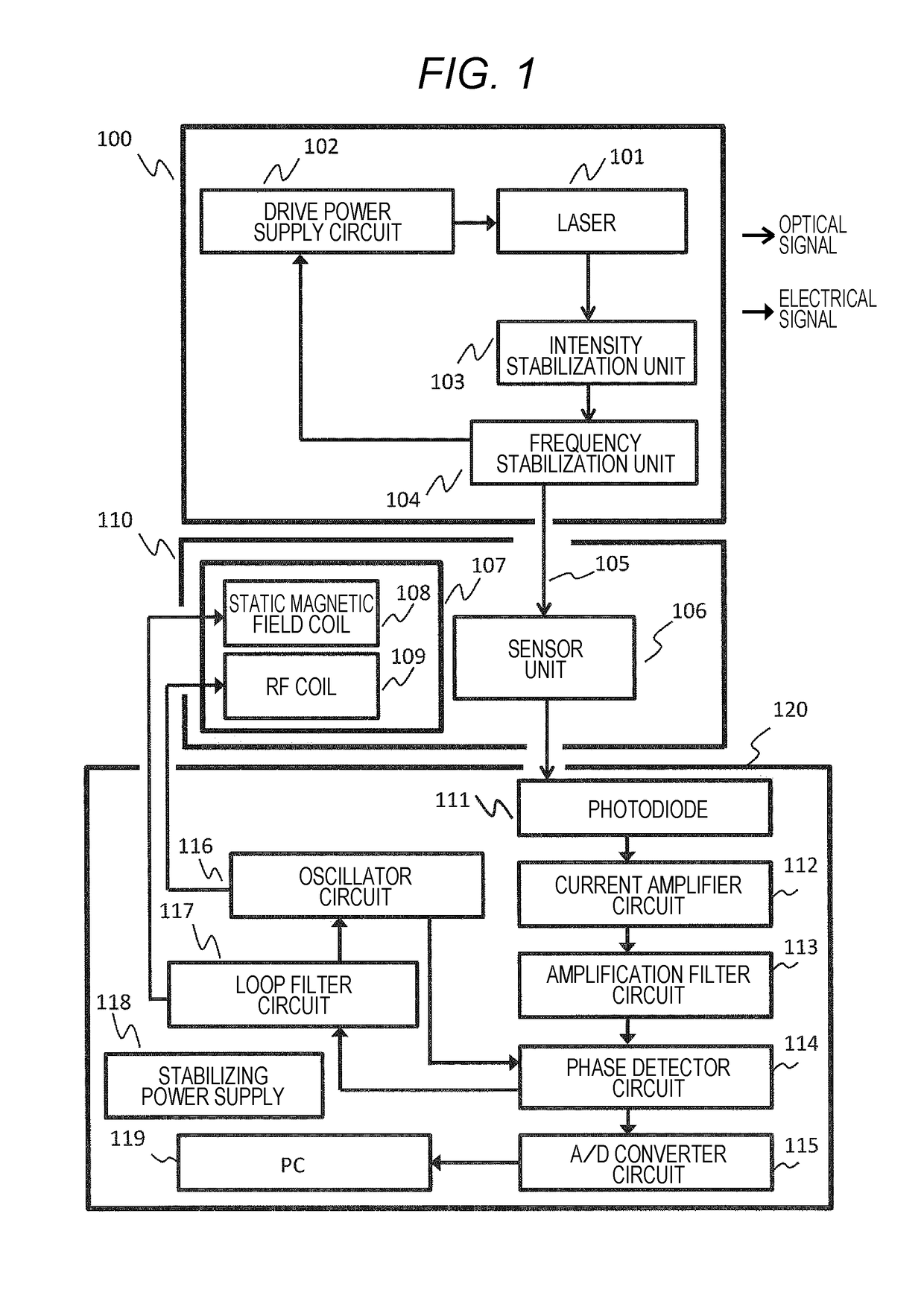
[0026]FIG. 1 illustrates an overall configuration of a magnetic field measurement device of an embodiment (Embodiment 1) of the present invention. The magnetic field measurement device includes a light source unit 100, a coil unit 107, a sensor unit 106, a magnetic shield unit 110, and a signal control processor 120. The light source unit 100 includes a laser 101, a drive power supply circuit 102, an intensity stabilization unit 103, and a frequency stabilization unit 104, and generates sensor pump light 105 to be introduced to a sensor glass cell in which alkali metal gas is encapsulated in the sensor unit 106. The light source is preferably a laser rather than a lamp in view of stability and performance. A laser is thus used for the light source in the present embodiment.

[0027]In the operation of the optically pumped magnetic sensor, the laser needs to oscillate in a single mode with an oscillation frequency including absorption lines (D1 line, D2 line) of alkali metals and a spec...

embodiment 2

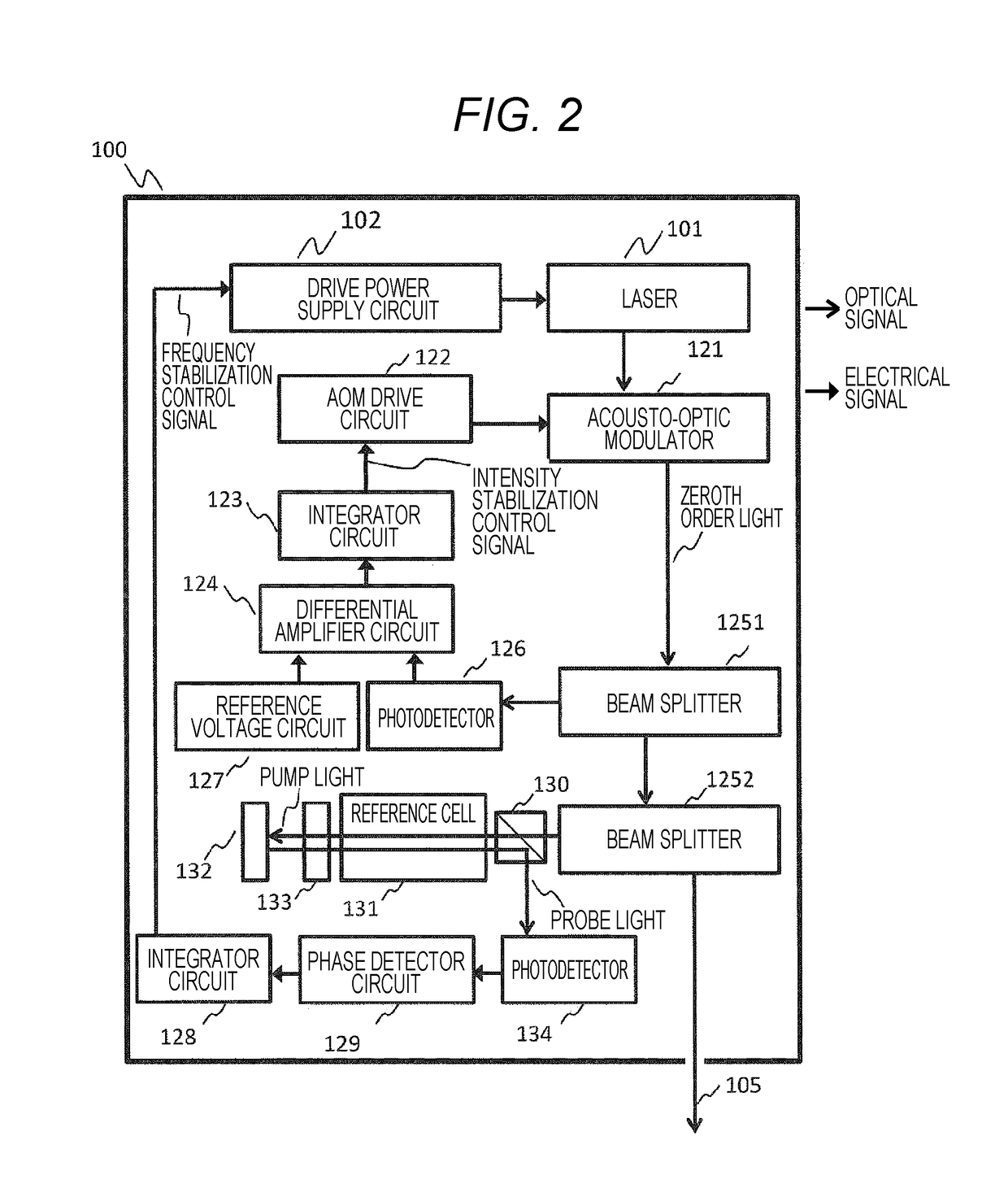
[0037]A magnetic measurement device of the second embodiment (Embodiment 2) of the present invention is different from that of Embodiment 1 in the configuration of the light source unit. The magnetic measurement device has the same configuration as that of the magnetic measurement device of Embodiment 1 illustrated in FIG. 1 except for the light source unit. Hereinafter, the configuration of a light source unit 140 of the magnetic measurement device of Embodiment 2 will be described with reference to FIG. 4. Components that are the same as those of the light source unit of Embodiment 1 illustrated in FIG. 2 will be designated by the same reference numerals. As compared to the light source unit of Embodiment 1, the difference lies in that the intensity stabilization unit constituted by the photodetector 126, the reference voltage circuit 127, the differential amplifier 124, the integrator circuit 123, the AOM drive circuit 122, and the acousto-optic modulator 121 is not inside of the...

embodiment 3

[0039]In the third embodiment (Embodiment 3) of the present invention, pump light introduced into the sensor glass cell is not single wavelength laser light as in Embodiment 1, but mixed light of laser light beams with a D1 line and a D2 line that are absorption lines of alkali metal used in the sensor glass cell is used as pump light.

[0040]FIG. 5 illustrates an overall configuration of a magnetic measurement device of Embodiment 3. Light source units 100-1 and 100-2 independent of each other are provided. The light source unit 100-1 includes a D1 line laser 101-1, an intensity stabilization unit 103-1, a frequency stabilization unit 104-1, and a drive power supply circuit 102-1, and the detailed configuration thereof is the same as that of the light source unit 100 of Embodiment 1 illustrated in FIG. 2. Similarly, the light source unit 100-2 also includes a D2 line laser 101-2, an intensity stabilization unit 103-2, a frequency stabilization unit 104-2, and a drive power supply cir...


PUM

PropertyMeasurementUnit
temperatureaaaaaaaaaa
magnetic field measurementaaaaaaaaaa
magnetic fieldaaaaaaaaaa

Abstract

A magnetic measurement device has a magnetic sensor including a glass cell having alkali metal gas encapsulated therein that is configured to detect a magnetic field using a magneto-optical characteristic of spin-polarized alkali metal. A laser light source is configured to generate pump light introduced into the magnetic sensor and a coil provided in the same magnetically shielded space as the magnetic sensor is configured to apply a static magnetic field and a RF magnetic field to the magnetic sensor. A signal processor is configured to perform lock-in detection of a light detection signal transmitted through the glass cell of the magnetic sensor, control an intensity of the static magnetic field and a frequency of the RF magnetic field generated by the coil according to a lock-in detection output, and obtain a measurement signal reflecting a magnetic field intensity of an object to be measured in the magnetically shielded space.

Description

TECHNICAL FIELD[0001]The present invention relates to a magnetic field measurement device utilizing the magneto-optical effect due to optical pumping.BACKGROUND ART[0002]In a magnetic field measurement device utilizing the magneto-optical effect due to optical pumping, a glass cell in which an alkali metal gas (such as potassium, rubidium, or cesium, for example) is enclosed is used as a sensor. A static magnetic field is applied to the glass cell, the energy level of alkali metal in the glass cell is subjected to Zeeman splitting, and interaction between light and magnetism caused by irradiating the glass cell with light obtained by changing the polarization state such as linearly polarized light, circularly polarized light or elliptically polarized light or light obtained by changing the intensity or the phase such as intensity modulated light or phase modulated light is used to detect the magnetism in the glass cell. The light source of pump light with which the glass cell is irr...

Claims


Application Information

Patent Timeline
Patent Type & Authority Patents(United States)
IPC IPC(8): G01R33/26G01N24/00H01S3/091
CPCG01R33/26G01N24/006H01S3/091
Inventor KAWABATA, RYUZOKANDORI, AKIHIKOOSABE, TAROSUZUKI, SEIICHIKAMADA, YUUDAI
Owner HITACHI LTD
Why Eureka
Try Eureka