
Method for manufacturing battery protection device and battery protection device

a battery protection and protection device technology, applied in secondary cell servicing/maintenance, batteries, cell components, etc., can solve the problems of high work time, high production cost, and high production cost, and achieve the effect of reducing the number of processes, reducing the defect rate, and improving productivity

Inactive Publication Date: 2018-12-25
TES CO LTD +1
View PDF14 Cites 0 Cited by
  • Summary
  • Abstract
  • Description
  • Claims
  • Application Information

AI Technical Summary

Benefits of technology

This method reduces the defect rate and the number of processes, enhancing productivity and reliability by simplifying the assembly and improving heat dissipation, thereby extending the life of the protection circuit module.

Problems solved by technology

Further, if heat generation is continued in the lithium-ion battery and a temperature thereof rises, a performance of the battery is deteriorated and also a risk of explosion is shown.
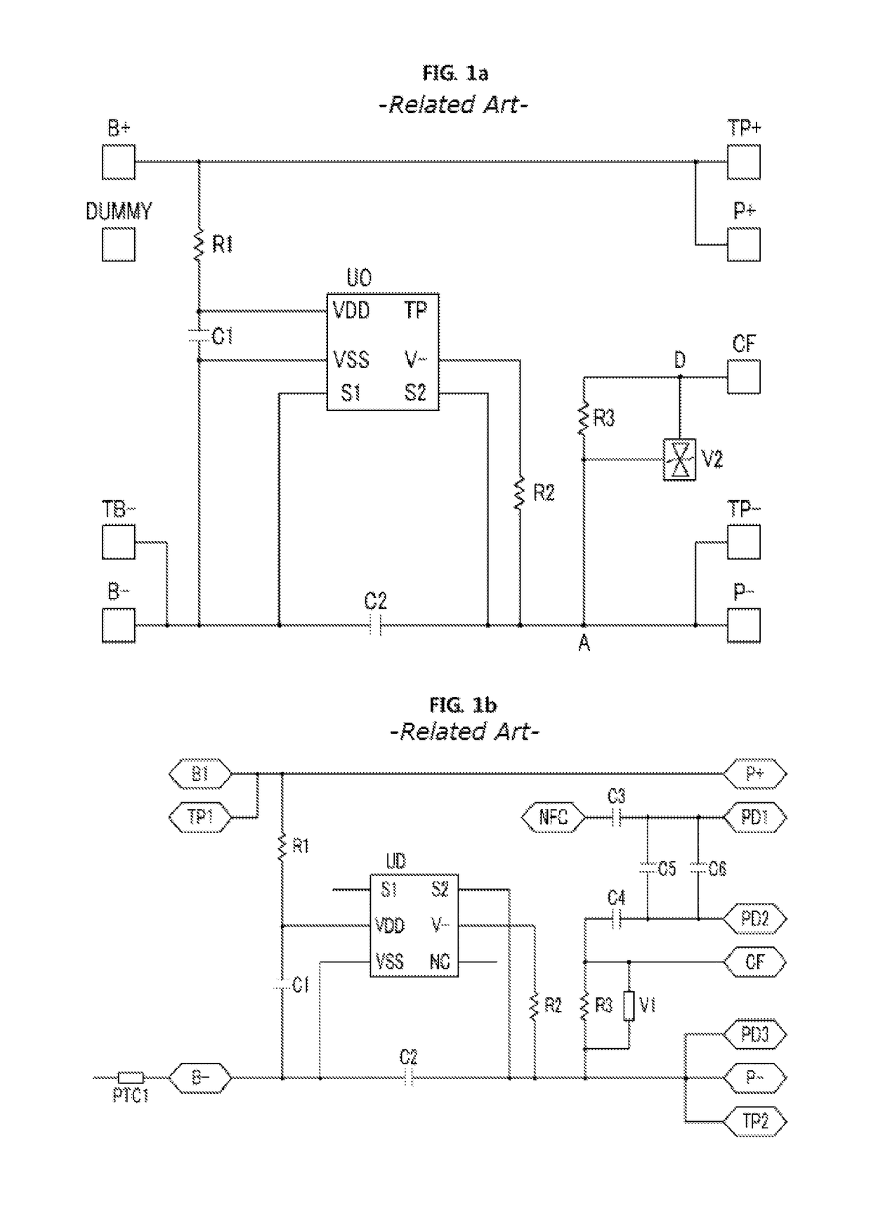
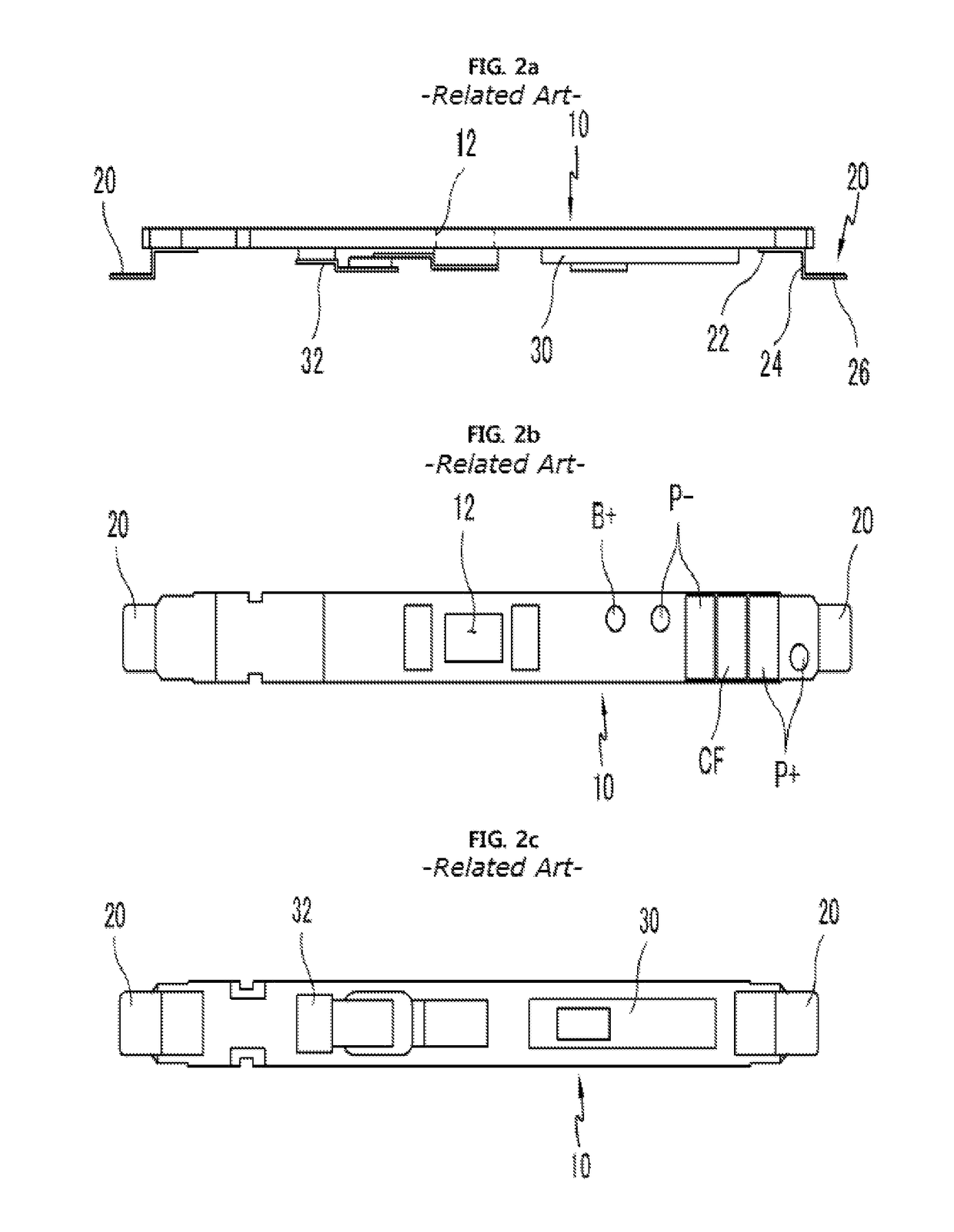
However, according to the conventional battery protection device as described above, the metallic spacers (20) separate from the PCB (10) have to be prepared and such metallic spacers (20) have to be soldered to the PCB (10) by means of SMT (Surface Mounting Technology), and thus there is a problem that much work time is required and the number of processes is increased, that is, a productivity is lowered.
Also, there is further problem that a defect rate increase since alignment in a soldering process by means of the SMT process is difficult.

Method used


Image

  • Method for manufacturing battery protection device and battery protection device
  • Method for manufacturing battery protection device and battery protection device
  • Method for manufacturing battery protection device and battery protection device

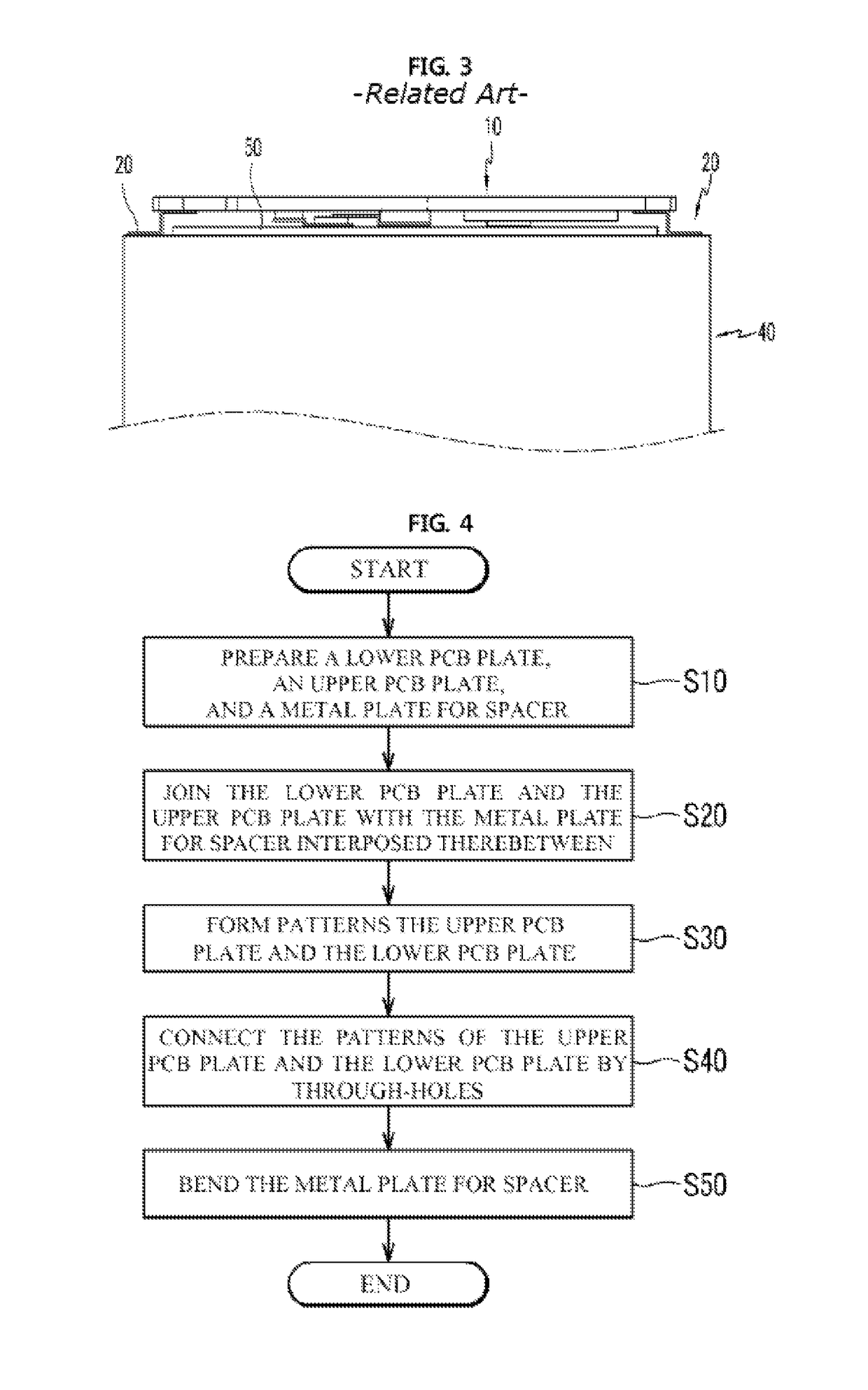
Examples


Embodiment Construction

[0027]In the following, detailed description will be made of preferred embodiments of a method for manufacturing a battery protection device and a battery protection device of the present invention with reference to the attached drawings.

[0028]FIG. 4 is a process flowchart for describing the method for manufacturing a battery protection device of the present invention. FIG. 5 shows sectional views for main steps of the method for manufacturing a battery protection device of the present invention. According to the method for manufacturing a battery protection device of the present invention, at step (S10), as illustrated in FIG. 5a, an upper PCB plate (100), a lower PCB plate (300) and a metal plate (200) functioning as a spacer (hereinafter, referred to as “metal plate for spacer”) are prepared. At the step (S10), the upper PCB plate (100) includes a synthetic resin plate (110) e.g. a hard PCB made of FR4, BT or polyimide, or a flexible PCB, with a metallic thin film (120), preferab...


PUM

PropertyMeasurementUnit
defect rateaaaaaaaaaa
temperatureaaaaaaaaaa
resistanceaaaaaaaaaa

Abstract

The present invention relates to a method for manufacturing a battery protection device and a battery protection device manufactured by the method, and more particularly, a method for manufacturing a battery protection device and a battery protection device which reduce a defect rate and also the number of processes, thus enhancing productivity.

Description

TECHNICAL FIELD OF THE INVENTION[0001]The present invention relates to a method for manufacturing a battery protection device and a battery protection device manufactured by the method, and more particularly, a method for manufacturing a battery protection device and a battery protection device which reduce a defect rate and also the number of processes, thus enhancing productivity.BACKGROUND OF THE INVENTION[0002]In recent, various portable terminals such as smartphones, smart pads, etc. are widely used, and as an electrical source for such portable terminals, a chargeable secondary cell (hereinafter, briefly referred to as “battery”) is generally used. A lithium-ion battery is a most widely-used battery in the portable terminal, but easily generates heat in a state of overcharge or overcurrent. Further, if heat generation is continued in the lithium-ion battery and a temperature thereof rises, a performance of the battery is deteriorated and also a risk of explosion is shown.[0003...

Claims


Application Information

Patent Timeline
Patent Type & Authority Patents(United States)
IPC IPC(8): H01M2/34H01M10/42H05K3/46H05K3/40H05K1/05H05K1/14
CPCH01M2/34H01M10/425H01M10/4257H05K3/46H05K3/4608H05K2201/041H01M2200/10H01M2200/108H05K1/053H05K1/144H05K3/4038H01M2200/00Y02E60/10
Inventor KIM
Owner TES CO LTD
Learn More