Microwave antenna applicator

a microwave antenna and microwave technology, applied in the field of open-ended frequency broadband microwave applicators, can solve the problems of low coupling factor, low power efficiency, and inability to use such systems with multiple antennas for signal detection across an ous consisting of e.g. a female breast, and achieves a wide range of beam width, less and reduced sidelobe and surface wave excitation.

Inactive Publication Date: 2019-01-22
RISMAN PER OLOV +2
View PDF15 Cites 0 Cited by
  • Summary
  • Abstract
  • Description
  • Claims
  • Application Information

AI Technical Summary

Benefits of technology

[0023]A ridged TE10 type waveguide has the further advantage of increased mode stability (i.e. other modes not being possible) over a wider frequency range. Furthermore, its lowest transmission operating frequency is also lower with given a dimension.
[0025]Such antenna applicators do, however neither provide a very narrow beamwidth of the propagation away from the applicator antenna nor minimised sideways excitation of surface waves along the OUS.

Problems solved by technology

As a consequence, using such systems with multiple antennas for signal detection across an OUS consisting of e.g. a female breast is therefore not possible.
Furthermore and due to the nearfield absorption, the system must either be resonant (i.e. single frequency) or have a very low coupling factor (i.e. a low power efficiency).
All antenna systems referred to so far are nearfield and suitable for ablation and other spotheating purposes, but not at all for multiple antenna signal transmission and measurements through an OUS for microwave tomographic purposes.
This considerably complicates the practical design.5. Patch antennas.—A typical example is described in the paper A Comparison of a Wide-Slot and a Stacked Patch Antenna for the Purpose of Breast Cancer Detection in IEEE TRANSACTIONS ON ANTENNAS AND PROPAGATION, VOL.
These are better in frequency broadband but suffer from impedance matching problems necessitating their immersion in an external liquid with comparable permittivity to that of the tissue.
However, the bolus must then be in very close contact with the OUS, which may cause patient discomfort.6. Vivaldi antennas.—A typical state-of-the-art example is described in the paper Balanced Antipodal Vivaldi Antenna With Dielectric Director for Near-Field Microwave Imaging in IEEE TRANSACTIONS ON ANTENNAS AND PROPAGATION, VOL.
However, the electromechanical design is complicated and requires very tight tolerances, resulting in quite expensive antennas.
This is since very small OUS irregularities at the contacting area have a large influence;cause minimal excitation of unwanted surface waves along the OUS periphery, such waves are characterised by an electric field component essentially perpendicular to the OUS surface;provide a narrow radiation lobe, also resulting in minimal excitation of unwanted surface waves along the OUS periphery;are uncomplicated and inexpensive to manufacture.

Method used


Image

  • Microwave antenna applicator
  • Microwave antenna applicator

Examples


first embodiment

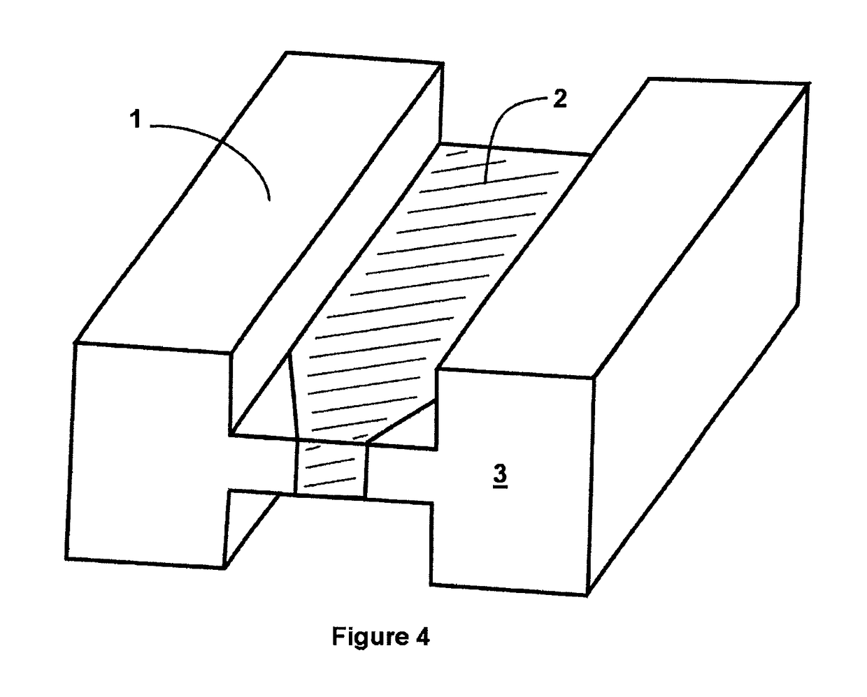
[0038]The function of the permittivity quotient of about ½ between the surrounding dielectric 1 and the higher-ε′ insert 2 and its shape is now described, in terms of electric field (E) geometry. At the opening of a constant cross section ridged waveguide with homogeneous filling, the E field wavefront will no longer be plane but be bulging outwards. This will strongly contribute to nearfield creation, i.e. fields no longer being parallel to the OUS surface. If, however, there is a filling in the ridge with higher ε′ than its surrounding, the central part of the wavefront will become somewhat retarded due to the general phenomenon of slower speed of propagation in higher-ε′ substances. This will result in a more plane-like wavefront being created and thus in turn less nearfied excitation; this constitutes the invention.

second embodiment

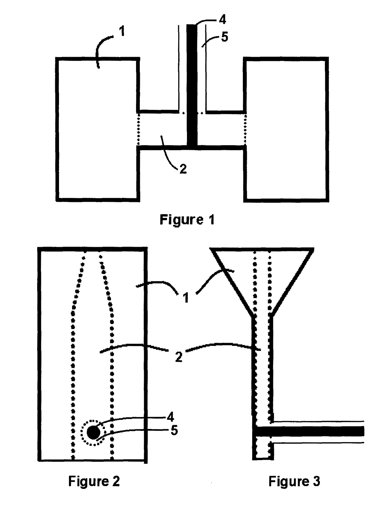
[0039]A further and second embodiment of the invention is that the front end part of the insert 2 is foursided frustrum pyramidal in only the wide (TE10 waveguide a) direction. The end tip width can be as shown in FIGS. 2 and 4. The length of this frustrum pyramid in the direction of wave propagation is typically in the order shown on FIGS. 2 and 3, i.e. in the order of the overall waveguide a dimension, and is for providing better impedance relationships in the varying cross section part, and for avoiding a too strong concentration of field energy to the ridge end facing the OUS.

[0040]As not shown in FIGS. 2, 3 and 4 a further embodiment is not to let the ceramic insert go all the way to the antenna opening. Positive reasons for this are that the field pattern will be smoother at the opening and thus reduce very local nearfield effects, and that a continuous material at the opening will provide better mechanical sealing. However, this distance should be small—in the order of 1 mm o...


PUM


Abstract

A new and comparatively small type of open-ended microwave applicators has been disclosed. They are for example suitable for transmission into and reception from contacting objects such as protruding human bodyparts for inhomogeneity detection by tomographic methods. The applicators according to the invention are of the dielectric-filled open-ended ridged rectangular TE10 type, with an insert filling the ridge and having a higher permittivity than the surrounding space. The shape of the insert can be as a frustrum pyramid towards the opening. The overall design promotes narrow beamwidths and minimizes nearfields and surface wave excitation.

Description

FIELD OF THE INVENTION[0001]The present invention is related to the field of open-ended frequency broadband microwave applicators. In particular, the applicators are intended for acting as transmitting and receiving antenna structures in close proximity to or contacting protruding human tissue such as female breasts, for tomographic investigations of irregularities caused by diseases such as cancer.[0002]However, there are also a number of other applications both in industry and for medical so-called hyperthermia treatments with the aim to partially and geometrically selectively destroy tissue or coagulate bloodflow during surgery.BACKGROUND OF THE INVENTION[0003]There are several kinds of prior art antennas described in the literature for the general purposes above. Examples are:[0004]1. Coaxial endfire applicator.—A typical example is described in U.S. Pat. No. 6,287,302. These have the advantage over more complicated systems by coaxial transmission lines being inherently frequenc...

Claims


Application Information

Patent Timeline
Patent Type & Authority Patents(United States)
IPC IPC(8): H01Q9/04A61B5/05H01Q13/24A61B18/04A61B18/18H01P3/123H01P3/12H01Q13/08A61N5/04A61B18/00
CPCH01Q9/0485A61B5/0507A61B18/1815H01P3/122H01Q13/085H01Q13/24H01P3/123A61N5/04A61B2018/00607A61B2018/183
Inventor RISMAN, PER OLOVOTTERSKOG, MAGNUSPETROVIC, NIKOLA
Owner RISMAN PER OLOV
Why Eureka
Try Eureka