
Removal of ozone from electrokinetic devices

a technology of electrokinetic devices and ozone removal, which is applied in the direction of positive displacement liquid engines, physical/chemical process catalysts, metal/metal-oxide/metal-hydroxide catalysts, etc., can solve the problems of commercial devices that were unsuccessful in preparing for ion-propulsion devices and the inability to apply

Active Publication Date: 2019-04-02
AIRANSWERS INC
View PDF3 Cites 2 Cited by
  • Summary
  • Abstract
  • Description
  • Claims
  • Application Information

AI Technical Summary

Benefits of technology

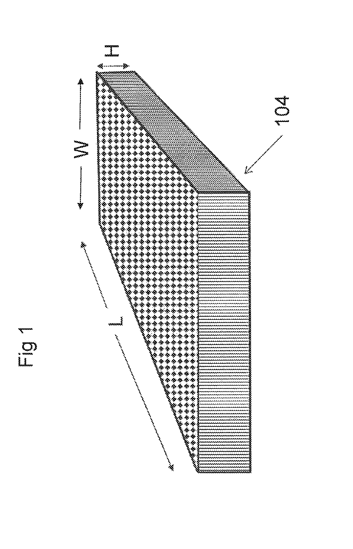
[0011]Ionic propulsion devices produce a relatively high air flow rate, and, since no moving parts are used in generating the air flow, there is no pressure gradient and extreme sensitivity to flow reduction by any device that creates resistance to flow. The flow is therefore easily impeded by any obstruction that will restrict flow. This application shows that, by use of a suitable pore size and thickness of a porous support medium, such as honey-comb ceramic fiber catalyst, a sufficient surface area exposure may be obtained which effectively destroys ozone without significantly impeding flow.

Problems solved by technology

Tatsushima and Sukura in U.S. Pat. No. 4,871,709 describe methods for fabrication of ozone cracking catalysts with fine structure that provides low resistance to flow, but do not anticipate applications to ion-propulsion devices.
In spite of efforts to limit ozone emission, the commercial devices were unsuccessful.

Method used


Image

  • Removal of ozone from electrokinetic devices
  • Removal of ozone from electrokinetic devices
  • Removal of ozone from electrokinetic devices

Examples


example 1

of the Device of the Current Invention

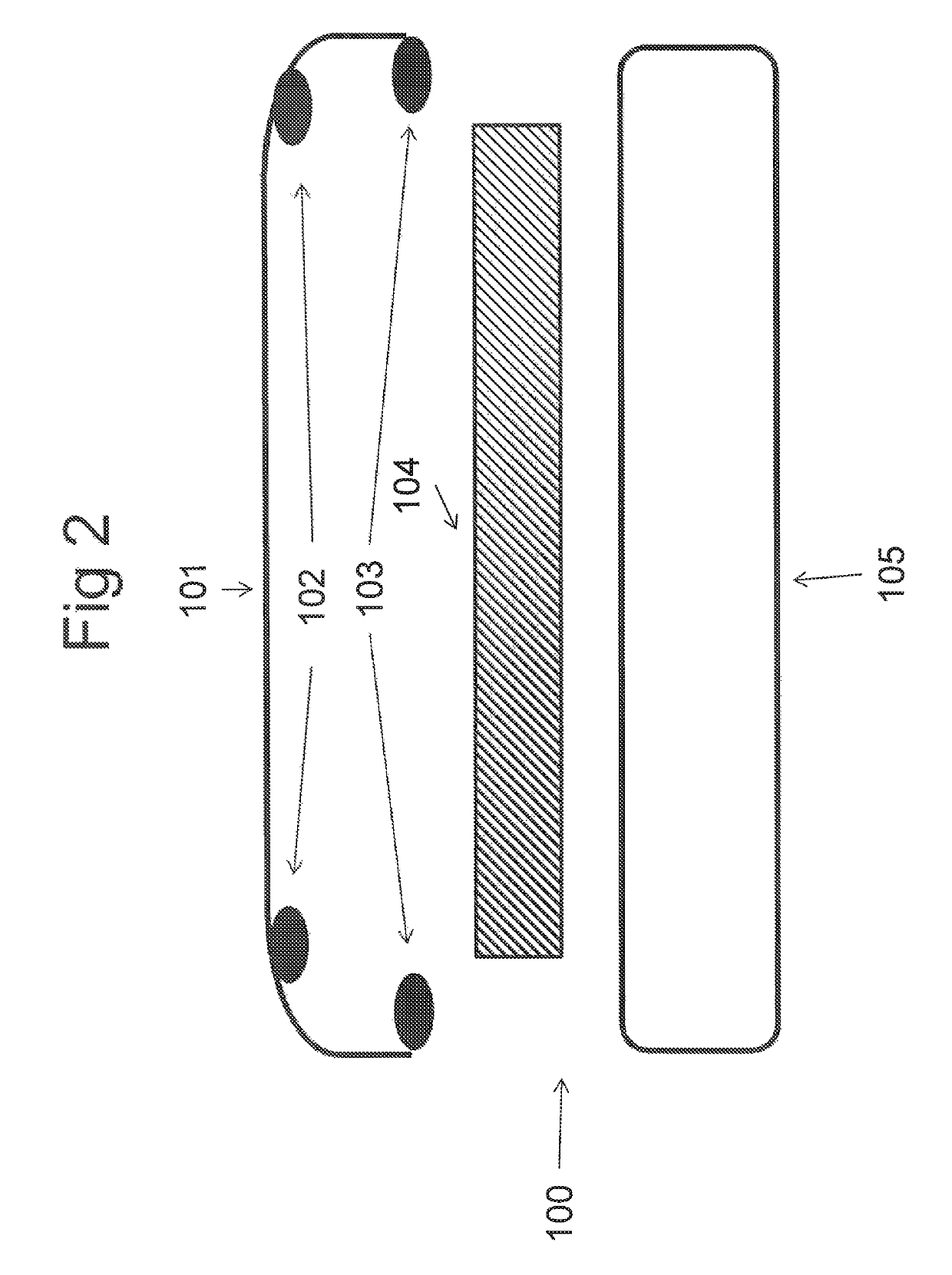
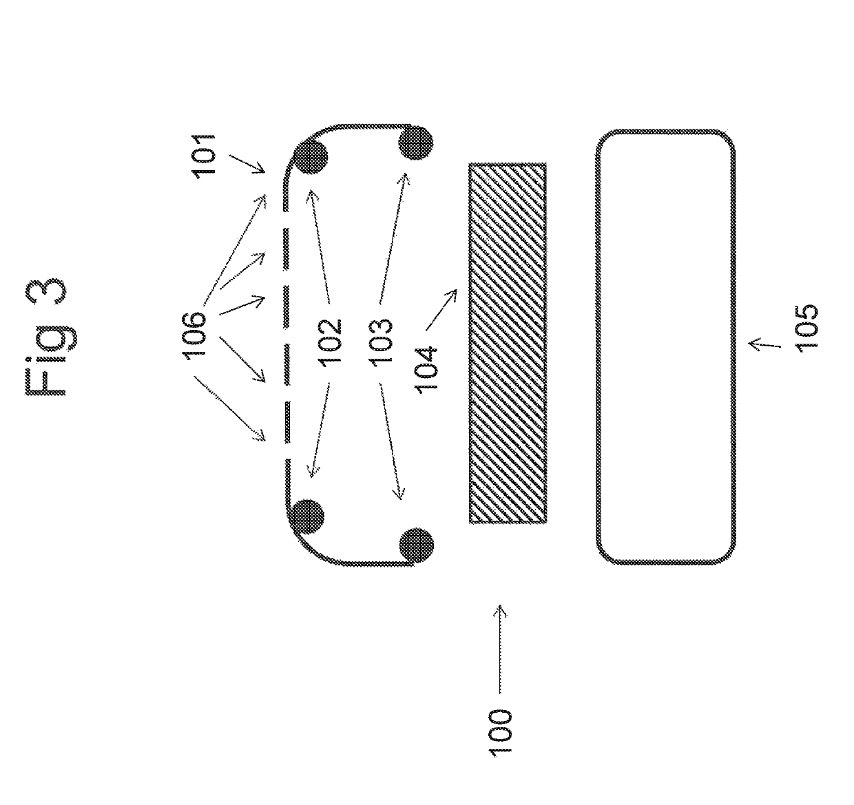
[0040]The Sharper Image Air Freshener model IU627JPN is used. This compact device has the disadvantage that air inflow and outflow are on the same side. There is thus mixing between the two air streams that reduces the efficiency of the device, since the same air is repeatedly re-processed. It is converted into a uni-directional flow device by cutting louvers into the rear side of the housing. The louvers are 4 mm×30 mm at 2 mm spacing. Eleven such louvers are cut with a milling machine adjacent to the length of the internal high voltage wire. Catalyst, fabricated according to the specifications of U.S. Pat. No. 4,871,709, was NHC-423 from Nikki-Universal, Tokyo, Japan, in the form of blocks 109 mm×52 mm×10 mm thick and being made of ceramic fiber aggregate coated with MnO2 with 200 cells / inch. The clamshell as in FIG. 7 was fabricated by 3D printing, and the dimensions were such that the four corners of the catalyst were wedged into place. Prio...

example 2

Catalyst on Air Flow Rate

[0041]Five devices are assembled as in Example 1. Air flow rate is determined with a hot wire anemometer (Heavy Duty Anemometer, Extech, Nashua, N.H.). The probe is placed at the center of each of the 11 inlet louvers created as in Example 1. The total volume flow is computed from the average of the air velocity at each position. The results for 5 devices are shown in Table 1.

[0042]

TABLE 1Air flow of devices (Liters / min)DeviceFlow without catalystFlow with catalyst11121192 991093102 9341311185106133Mean110115

[0043]The mean difference of 5 liters / min is not considered significant. Similar evaluation of the catalyst NHC-453 with 500 cells per inch and 5 mm thickness resulted in a reduction of flow rate by of 40%, and complete destruction of ozone in effluent. There is thus an optimal combination of cells per inch of catalyst and thickness of catalyst for ozone destruction and flow rate.

[0044]The prior art suggests an extremely open structure needs to be used i...


PUM

PropertyMeasurementUnit
thicknessaaaaaaaaaa
thicknessaaaaaaaaaa
thicknessaaaaaaaaaa

Abstract

Electrokinetic devices and methods are described with the purpose of propelling a dielectric fluid medium, usually air, and optionally collecting assayable agents from the medium. Electrokinetic flow may be induced by the use of plasma generation at high voltage electrodes and consequent transport of charged particles in an electric voltage gradient. The generation of electrokinetic flow has the disadvantage that certain amounts of ozone may be formed in the process. Methods and devices are described herein where suitable catalysts can be combined with the electrokinetic device in such a way that ozone is effectively destroyed in the effluent flow without compromising the amount of flow.

Description

FIELD OF THE INVENTION[0001]The present invention relates to the propulsion of fluid and collection of and sampling of assayable agents in a dielectric medium. This includes ionic propulsion devices for air cleaning and sampling air for agents whose presence or absence is determinable by bio-specific assays. While the present invention is equally applicable to air cleaning or air sampling devices, we have a particular interest in the application to the field of capture of aerosol particles for analytical purposes. The field includes sampling of air for biological agents, direction to, and deposition on, a collection means for an assay device. The agent-specific assays may include immunoassays, nucleic acid hybridization assays, or any other assays entailing ligand-antiligand interactions. Assays may include, but are not limited to, detection means which are colorometric, fluorescent, turbidimetric, electrochemical or voltammetric. Agents assayed include, but are not limited to, bio-...

Claims


Application Information

Patent Timeline
Patent Type & Authority Patents(United States)
IPC IPC(8): F04B19/00B01J35/06B01J35/00B01J23/34F04D33/00B01J37/02B01J35/04
CPCB01J23/34F04D33/00B01J37/0215B01J35/04
Inventor GORDON, JULIAN
Owner AIRANSWERS INC
Learn More