Fibre optic distributed sensing

Active Publication Date: 2019-04-02
OPTASENSE HLDG LTD
View PDF4 Cites 18 Cited by
  • Summary
  • Abstract
  • Description
  • Claims
  • Application Information

AI Technical Summary

Benefits of technology

[0012]Embodiments of the present invention aim to provide methods and apparatus for distributed

Problems solved by technology

DTS is a useful technique with a range of applications but most DTS systems require relatively long time averages to provide the desired accuracy, meaning such DTS systems are less useful for detecting relatively rapid changes in temperature.
A mechanical vibration of the fibre, such as caused by an incident acoustic wave, will alter the distribution of scattering sites resulting in a detectable change in the properties of the Raleigh backscattered light.
As the backscatter from the various scattering sites within the sensing portion of fibre will interfere to produce the resulting intensity, a change in optical path length will vary the degree of interference and thus result in a change in backscatter intensity.
One issue with such sensors however is that the relative intensity change in response to a given input stimulus will vary from channel to channel and can also vary for a given channel over time.
This means t

Method used


Image

  • Fibre optic distributed sensing
  • Fibre optic distributed sensing
  • Fibre optic distributed sensing

Examples


Embodiment Construction

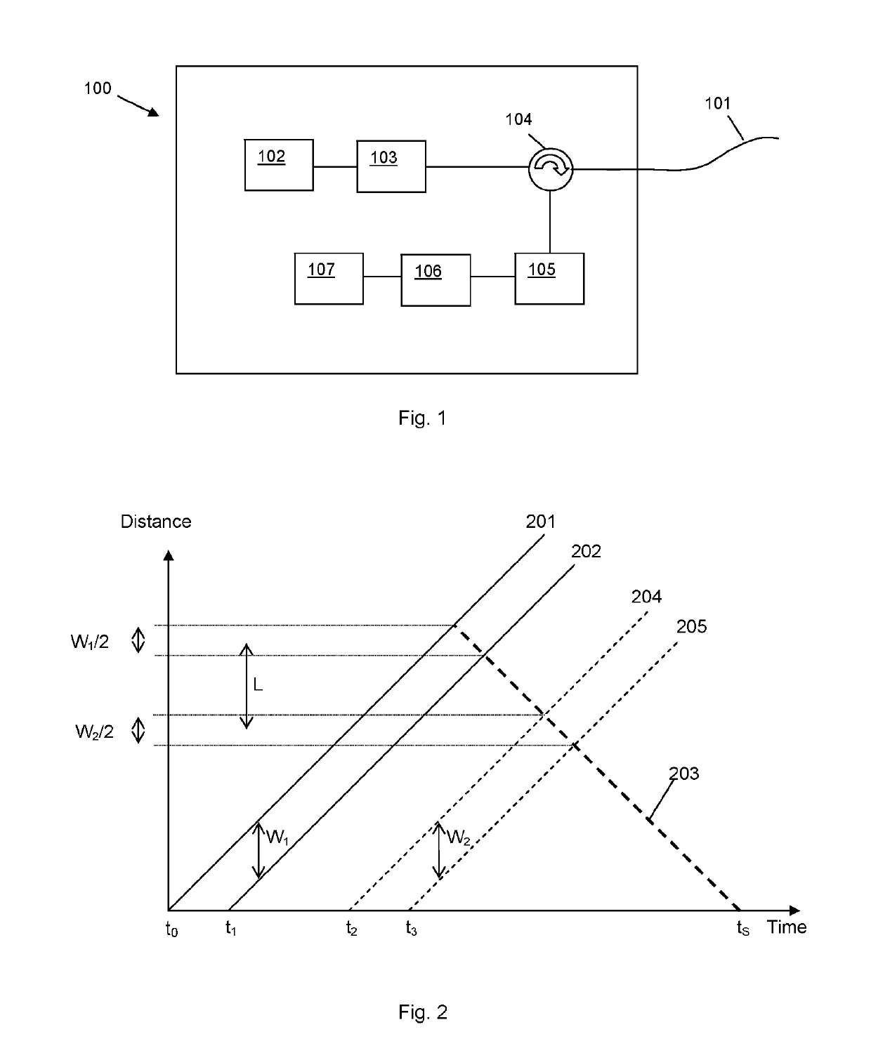
[0049]FIG. 1 shows a schematic of a general distributed fibre optic sensing arrangement. A length of sensing fibre 101 is removably connected at one end to an interrogator 100. The sensing fibre is coupled to an output / input of the interrogator using conventional fibre optic coupling means. The interrogator unit is arranged to launch pulses of coherent optical radiation into the sensing fibre 101 and to detect any radiation from said pulses which is backscattered within the optical fibre. For a Rayleigh scattering based distributed acoustic sensing (DAS) apparatus the detector will detect radiation which has been Rayleigh backscattered from within the fibre and which is thus at the same frequency as the interrogating radiation. To generate the optical pulses the interrogator unit 100 comprises at least one laser 102. The output of the laser may be received by an optical modulator apparatus 103. Note that as used herein the term “optical” is not restricted to the visible spectrum and...


PUM


Abstract

This application describes methods and apparatus for distributed fiber optic sensing that reduce or compensate for the effects of laser phase noise. The method involves repeatedly interrogating an optical fiber (101), where each interrogation involves launching at least one interrogating pulse into the optical fiber; detecting optical radiation which is backscattered from within the fiber, and forming a measurement signal from a plurality of sensing portions of the fiber. The method involves forming a laser noise template based on the measurement signals within a frequency band of interest from a first set of said sensing portions; and applying a correction to the measurement signals from said plurality of sensing portions based on said laser noise template. The first set of sensing portions may be temperature and/or strain stable portion from an isolated section of fiber (301, 303) or may comprise a selected set of sensing portions, which may include substantially all the sensing portions, which are averaged to form the laser phase noise template. For a phase based DAS type sensor the laser phase noise template may simply be subtracted from the measurement signals. For an intensity based sensor it may be necessary to polarity align and normalize the signals of the first set before averaging and then determine a gain-time profile for each sensing portion prior to applying the correction.

Description

FIELD OF THE INVENTION[0001]This application relates to fibre optic distributed sensing, and especially to methods and apparatus for detecting and / or correcting for laser phase noise.BACKGROUND OF THE INVENTION[0002]Fibre optic sensing is a known technique where an optical fibre, deployed as a sensing fibre, is interrogated with interrogating radiation and radiation which emerges from the fibre is detected and analysed to determine environmental changes acting on the optical fibre. Some fibre optic sensors rely on deliberately introduced features within the fibre, e.g. fibre Bragg gratings or the like, to induce reflection from a point in the fibre. In a fibre optic distributed sensor however the radiation which is backscattered from inherent scattering sites within the fibre is detected. The sensing function is thus distributed throughout the fibre and the spatial resolution and arrangement of the various sensing portions depends on the characteristics of the interrogating radiatio...

Claims


Application Information

Patent Timeline
IPC IPC(8): G01D5/353G01D18/00G01K11/32G01L1/24
CPCG01D5/35361G01D18/00G01L1/246G01K11/3206G01K11/32
Inventor CRICKMORE, ROGERKU, EMERY
Owner OPTASENSE HLDG LTD
Why Eureka
Try Eureka