
Systems and methods for improved physiological monitoring

a physiological monitoring and system technology, applied in the field of physiological monitoring, can solve the problems of inconvenient routine use outside hospitals, prohibitively expensive and/or large conventional physiological monitoring devices, and complicated processing,

Inactive Publication Date: 2019-07-02
GENERAL ELECTRIC CO
View PDF21 Cites 2 Cited by
  • Summary
  • Abstract
  • Description
  • Claims
  • Application Information

AI Technical Summary

Problems solved by technology

However, such conventional physiological monitoring devices are often too large and / or are prohibitively expensive for routine use outside hospitals.
However, use of these portable devices entails direct skin contact, complicated processing, insufficient monitoring capabilities, considerable power consumption, and / or need for a trained operator.
Furthermore, measurements made using the conventional devices are highly susceptible to motion artifacts caused by patient motion and / or ambient vibrations.
Although such empirical models attempt to correlate the magnetic field measurements to certain physiological parameters, the empirical models do not account for certain magnetic properties such as magnetization relaxation of the blood.
Furthermore, the empirical models fail to provide an accurate representation of the blood flow, geometry, and magnetic interaction between the blood and the generated magnetic field.
Since these conventional models disregard effects of certain magnetic properties of blood on the magnetic field measurements, values of the physiological parameters determined using such conventional monitoring methods may be inaccurate, and thus, unsuitable for clinical use.

Method used


Image

  • Systems and methods for improved physiological monitoring
  • Systems and methods for improved physiological monitoring
  • Systems and methods for improved physiological monitoring

Examples


Embodiment Construction

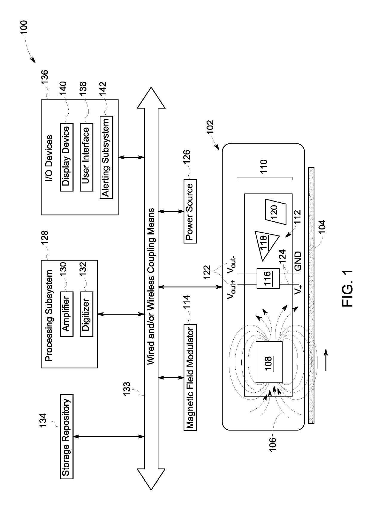
[0017]The following description presents systems and methods for enhanced monitoring of physiological parameters of a patient. Particularly, certain embodiments illustrated herein describe easy to use, non-invasive, small footprint, low-weight, ruggedized, and low-power monitoring systems and methods. Embodiments of the monitoring systems and methods employ a varying magnetic field and an array of magnetic sensors for monitoring physiological parameters of the patient with improved accuracy. Specifically, the embodiments described herein present a wearable patient monitor suitable for tracking a medical condition of the patient and / or for providing continual assessment of an effect of medication, exercise, and lifestyle changes on the patient in real-time in a hospital, clinic, home, and / or ambulatory setting.

[0018]Additionally, embodiments of the present system and method also provide a three-dimensional (3D) coupled mathematical model that accurately defines relationships between ...


PUM

PropertyMeasurementUnit
sizeaaaaaaaaaa
sizeaaaaaaaaaa
sizeaaaaaaaaaa

Abstract

A system and method for monitoring a subject are presented. The system includes a sensing device including at least one magnetic source to generate a magnetic field and an array of magnetic sensors disposed within the magnetic field. The sensor array obtains a plurality of magnetic field measurements at a plurality of locations along a vessel carrying a fluid including one or more magnetic particles. Further, the system includes a processing subsystem communicatively coupled to the sensing device, where the processing subsystem determines variations in the measurements caused by magnetization-relaxation of the magnetic particles based on a coupled model that defines behavior of the fluid in the varying magnetic field based on principles of magnetization-relaxation, bulk motion of the magnetic particles towards a determined gradient of the magnetic field, magnetostatics, and conservation of momentum. The processing subsystem estimates values of one or more desired parameters based on the determined variations.

Description

BACKGROUND[0001]Embodiments of the present specification relate generally to physiological monitoring, and more particularly to systems and methods for enhanced estimation of physiological parameters using an array of magnetic sensors.[0002]Continual monitoring of a patient's physiological parameters such as vital signs and / or blood flow characteristics allows for early detection of physiological anomalies, thus providing timely alerts for life saving interventions. Particularly, routine use of multi-parameter monitors in trauma, surgery, and intensive-care unit settings has greatly improved medical outcomes in recent times. By way of example, pulse oximeters, ultrasonic flow meters, and pressure cuff sensors are routinely used for monitoring oxygen saturation (SpO2), cardiac output, and / or blood pressure to aid in detection of life-threatening medical conditions such as arterial hypoxemia, hypovolemia, and / or internal bleeding. However, such conventional physiological monitoring de...

Claims


Application Information

Patent Timeline
Patent Type & Authority Patents(United States)
IPC IPC(8): A61B5/05G01N27/74A61B5/145G01F1/712G01R33/09A61B5/021A61B5/024A61B5/0265A61B5/029G01F1/56A61B5/0205A61B8/08G01N33/18G01N33/22G01N33/26G01N33/49A61B5/00
CPCG01N27/74A61B5/024A61B5/0205A61B5/029A61B5/0265A61B5/05A61B5/0515A61B5/14542A61B8/488G01F1/56G01F1/712G01N33/18G01N33/225G01N33/26G01N33/49G01N33/4925G01R33/096A61B5/021A61B2562/043A61B5/02416A61B5/6824
Inventor NAGARKAR, KAUSTUBH RAVINDRAASHE, JEFFREY MICHAELHUBER, WILLIAM HULLINGERCOUTURE, AARON JUDYATALLA, ASHRAF SAID
Owner GENERAL ELECTRIC CO
Learn More