Server rack heat sink system with combination of liquid cooling device and auxiliary heat sink device

a technology of liquid cooling and server rack, which is applied in the direction of cooling/ventilation/heating modifications, climate sustainability, and modifications using liquid cooling, can solve the problems of large power consumption of air conditioning systems, increase in device power consumption, and increase in heat generated by devices inside the cabinet, so as to achieve no local overheating, high cooling efficiency, and good

Active Publication Date: 2019-07-16
GUANGDONG SHENLING ENVIRONMENT SYST CO LTD
View PDF22 Cites 6 Cited by
  • Summary
  • Abstract
  • Description
  • Claims
  • Application Information

AI Technical Summary

Benefits of technology

[0012]An object of the present invention is to overcome one of the above deficiencies in the art and provide a server heat dissipation system comprising a liquid cooling device in combination with an auxiliary heat dissipation device, which provides high cooling efficiency and good effect, causes no local overheating, and requires no reconstruction to the cabinet.

Problems solved by technology

However, power consumption of the devices also increases, resulting in more heat generated by the devices inside the cabinet.
For a room that does not utilize fresh air, cooling is required for the whole year, which results in a huge power consumption by the air conditioning system, which accounts for about 40%-50% of the total power consumption in the data room.
However, this mode can no longer meet the cooling requirement for high density cabinets in a modernized computer room, and causes problems related to local overheating, high power consumption, and too high energy consumption by air conditioners in the room, and loud noise.
In the meantime, precise air conditioning in the room requires repeated humidification and dehumidification operations, or providing a specialized dehumidifier to perform humidity and dew-point control in the room, so as to ensure that no condensation occurs inside the devices, which results in decrease in efficiency of the air conditioning system, and increase in power consumption.
If the heat dissipation problem is not well solved, safety operation of the devices in the room will be greatly affected.
However, the introduction of outdoor cold air makes it hard to ensure the cleanliness and humidity of the indoor air, which brings safety risks and requires lots of maintenance in future operations.
However, its disadvantage is that it requires relatively high initial investment, complex structures for the heat exchanger, is easy to be blocked, and requires regular cleaning and lots of maintenance.
However, due to the limitation in heat dissipation efficiency of air cooling, it is hard for a high power server to be utilized under more than 15 kW per cabinet.
However, this heat dissipation solution currently only exists in university laboratories and very few corporations for internal small-scale study, and has not yet been practicalized.
However, cabinet manufactures normally only provide standardized production, and have not mastered key technologies related to designing for a liquid distributing system, therefore, they cannot provide server users with a cabinet having inside a liquid distributing system.
Especially for the upgrade of old computer rooms, in order to utilize a liquid heat dissipation solution, all the cabinets have to be replaced with cabinets having a liquid distributing system, which requires a very large amount of work and a very high cost, greatly affecting the development and popularization of liquid cooling technique.
If traditional air cooling is still used in the auxiliary cooling device, local overheating may occur very easily in the cabinet, affecting the life of the elements in the server, which is also a problem that cannot be ignored in the development and popularization of high density liquid cooling servers.
Although liquid heat dissipation is also used in this patent application, the heat in the server cannot entirely be taken out by the liquid cooling system.
Therefore, there still exist problems such as local overheating and short life.
However, the cooling device in the first circulation loop performs heat conduction to the air inside the whole cabinet, instead of performing heat conduction directly to the heat generating chips in the server, which results in a low cooling efficiency and poor effect.
Thus a specialized heat exchanger is required to transfer the heat accumulated during operation of the first pump, which undoubtedly brings a burden to the system and thus further reduces the cooling efficiency of the system.
Therefore, the heat dissipation solution provided in this patent application is not enough.

Method used


Image

  • Server rack heat sink system with combination of liquid cooling device and auxiliary heat sink device
  • Server rack heat sink system with combination of liquid cooling device and auxiliary heat sink device
  • Server rack heat sink system with combination of liquid cooling device and auxiliary heat sink device

Examples


example 1

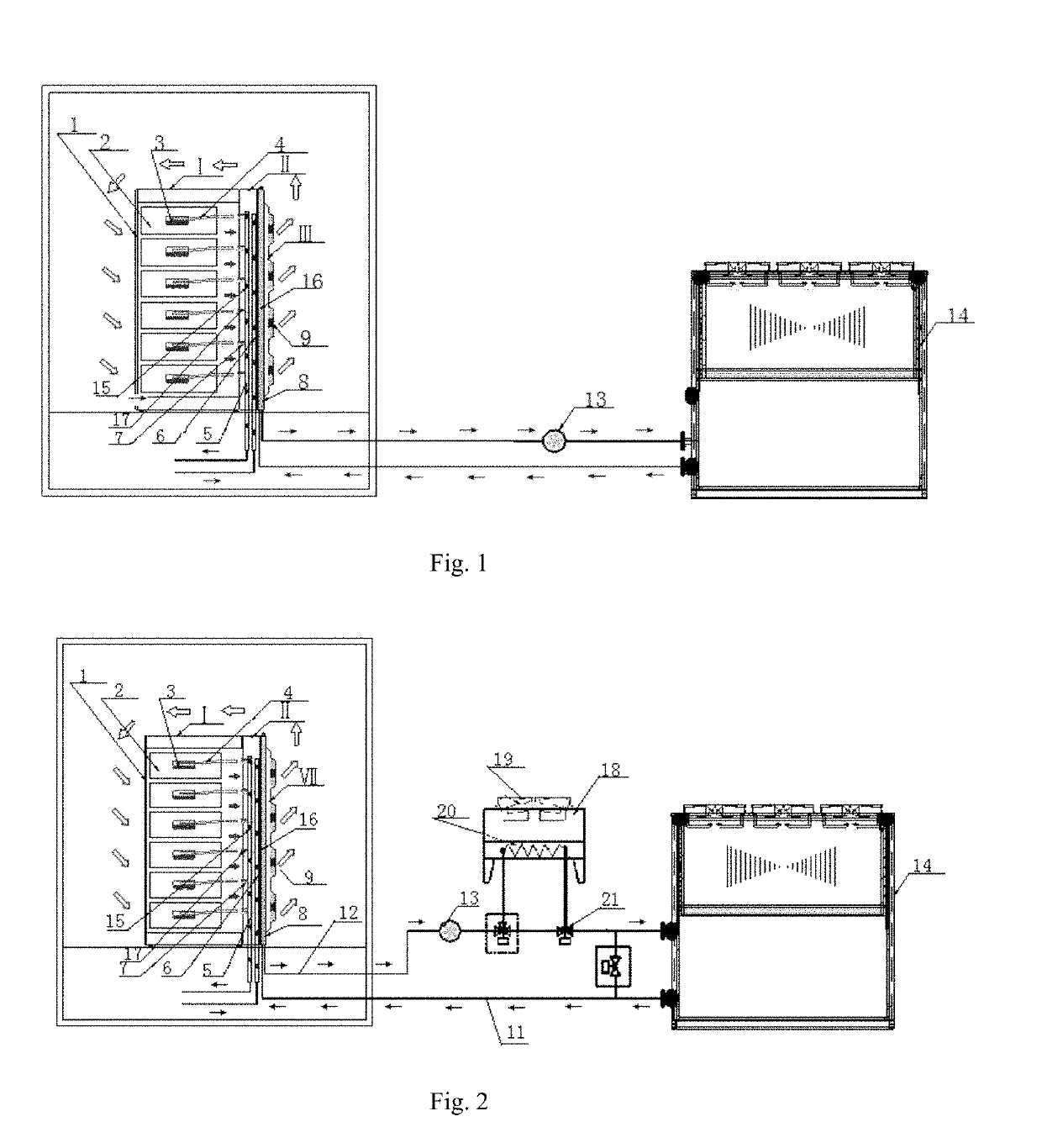
[0130]As shown in FIG. 1, a server cabinet heat dissipation system is provided, comprising a liquid cooling server cabinet I, a liquid cooling device II, and a door-type cold water heat exchange device III. The liquid cooling server cabinet I comprises a cabinet body 1 and a liquid cooling server 2. A server chip 3 and a liquid heat dissipater 4 are provided inside the liquid cooling server 2. The liquid cooling device II comprises a distributor 6, a collector 5 and a connecting branch pipe 7. The door-type cold water heat exchange device III comprises a cold water heat exchanger 8, a fan 9, a pump 13 and a chiller 14. The distributor 6 and the collector 5 of the liquid cooling device II are respectively connected with the liquid cooling server 2 by the liquid inlet pipe 7 and an liquid outlet pipe 17. The cold water heat exchanger 8 of the door-type cold water heat exchange device III is installed on the liquid cooling device II.

[0131]The liquid cooling device II is externally inst...

example 2

[0140]As shown in FIG. 2, a server heat dissipation system is provided, comprising a liquid cooling server cabinet I, a liquid cooling device II, and a natural-cooling cold water device VII. The liquid cooling server cabinet I comprises a cabinet body 1 and multiple liquid cooling servers 2 provided inside the cabinet body. The liquid cooling server 2 is provided with a server chip 3. The liquid cooling device II comprises a liquid heat dissipater 4, a distributor 6, and a collector 5. The distributor 6 and the collector 5 are respectively connected with the liquid heat dissipater 4 inside the liquid cooling server by a plurality of liquid inlet pipes 7 and a plurality of liquid outlet pipes 17. The liquid heat dissipater 4 contacts the server chips 3 or is provided adjacent to the server chips 3. The natural-cooling cold water device VII comprises a cold water heat exchanger 8 provided on the liquid cooling device, a fan 9 installed at an air outlet side of the cold water heat exch...

example 3

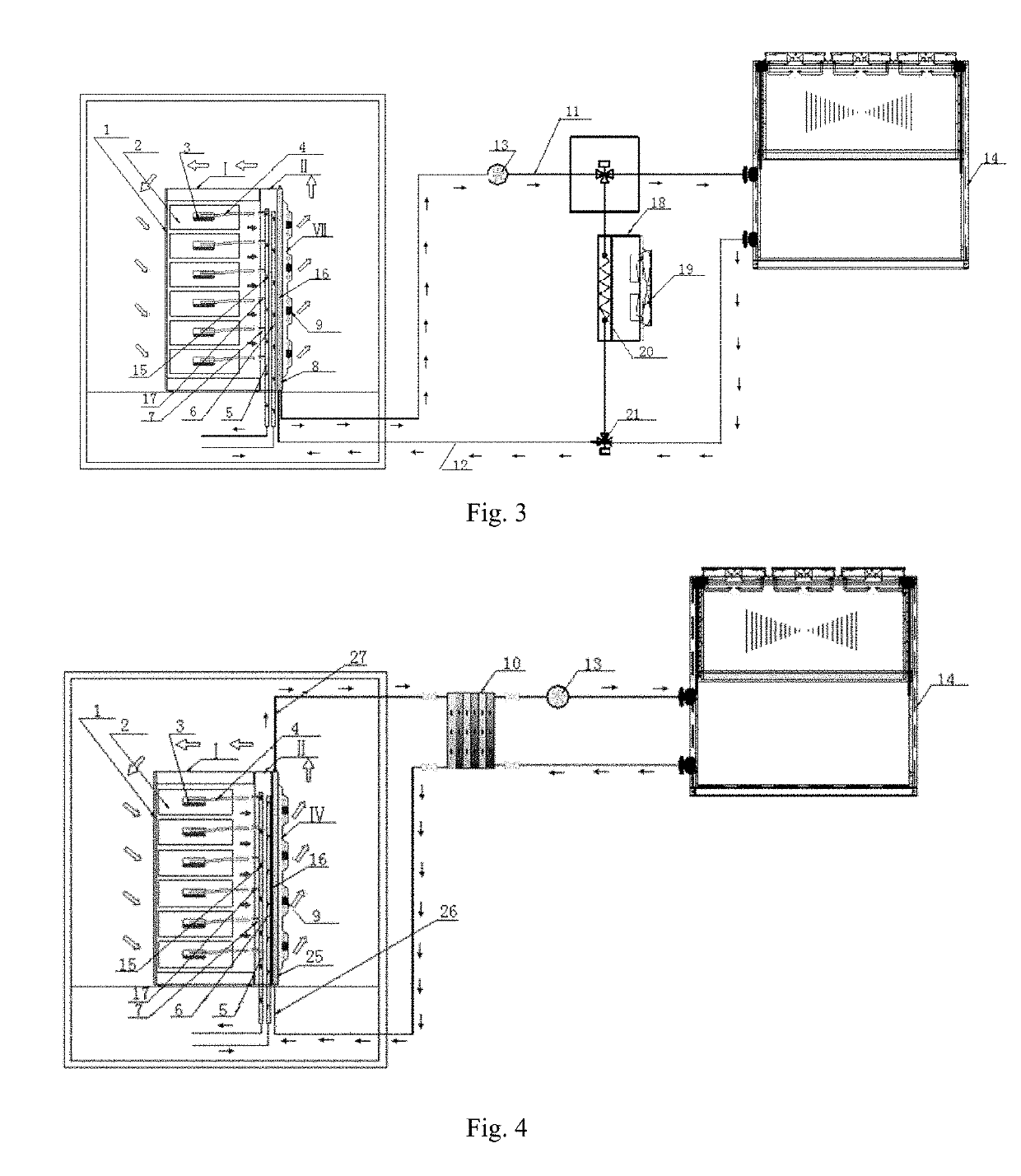
[0154]As shown in FIG. 3, a server heat dissipation system is provided, comprising a liquid cooling server cabinet I, a liquid cooling device II, and a natural-cooling cold water device VII. The liquid cooling server cabinet I comprises a cabinet body 1 and multiple liquid cooling servers 2 provided inside the cabinet body. The liquid cooling server 2 is provided with a server chip 3. The liquid cooling device II comprises a liquid heat dissipater 4, a distributor 6, and a collector 5. The distributor 6 and the collector 5 are respectively connected with the liquid heat dissipater 4 inside the liquid cooling server by a plurality of liquid inlet pipes 7 and a plurality of liquid outlet pipes 17. The liquid heat dissipater 4 contacts the server chips 3 or is provided adjacent to the server chips 3. The natural-cooling cold water device VII comprises a cold water heat exchanger 8 provided on the liquid cooling device, a fan 9 installed at an air outlet side of the cold water heat exch...


PUM


Abstract

A server heat dissipation system is provided, comprising a liquid cooling server cabinet comprising a cabinet body and multiple liquid cooling servers provided inside the cabinet body, wherein it is provided with a liquid cooling device to perform direct liquid cooling to the liquid cooling servers, and with an auxiliary heat dissipation device to perform auxiliary heat dissipation to the liquid cooling servers. The present invention provides high density cooling, high heat exchange efficiency, no local overheating, small space occupied, high reliability, low noise, and long life.

Description

FIELD OF THE INVENTION[0001]The present invention relates to a heat dissipation system for server cabinet, and in particular to a server heat dissipation system comprising a liquid cooling device in combination with an auxiliary heat dissipation device.BACKGROUND OF THE INVENTION[0002]As continuing increase of high density cabinets in the IDC internet data center room, devices' integration level increases, and so does their processing ability. However, power consumption of the devices also increases, resulting in more heat generated by the devices inside the cabinet. According to statistics, current cabinet servers in huge IDC rooms produce a lot of heat and basically operate 8760 h for a whole year. For a room that does not utilize fresh air, cooling is required for the whole year, which results in a huge power consumption by the air conditioning system, which accounts for about 40%-50% of the total power consumption in the data room.[0003]Conventional ways for air supply in a data...

Claims


Application Information

Patent Timeline
Patent Type & Authority Patents(United States)
IPC IPC(8): H05K7/20
CPCH05K7/20636H05K7/2079H05K7/20309H05K7/20318H05K7/20681H05K7/20736H05K7/20772H05K7/20781H05K7/20327Y02D10/16Y02D10/00
Inventor PAN, ZHANHUALI, MINHUACHEN, HUAXIE, CHUNHUIOUYANG, TIZHANG, XUEWEIQIU, YUQUN
Owner GUANGDONG SHENLING ENVIRONMENT SYST CO LTD
Why Eureka
Try Eureka