Controlling structural phase transitions and properties of two-dimensional materials by integrating with multiferroic layers

a two-dimensional material and phase transition technology, applied in the field of heterostructures, can solve the problems of inability to change, several drawbacks of conventional methods,

Active Publication Date: 2019-09-03
UNITED STATES OF AMERICA
View PDF10 Cites 8 Cited by
  • Summary
  • Abstract
  • Description
  • Claims
  • Application Information

AI Technical Summary

Problems solved by technology

However, the conventional methods suffer from several drawbacks.
The lateral size of such a gate is determined by the limits of the lithography used to produce it, and it cannot be changed once it is fabricated.

Method used


Image

  • Controlling structural phase transitions and properties of two-dimensional materials by integrating with multiferroic layers
  • Controlling structural phase transitions and properties of two-dimensional materials by integrating with multiferroic layers
  • Controlling structural phase transitions and properties of two-dimensional materials by integrating with multiferroic layers

Examples


example 1

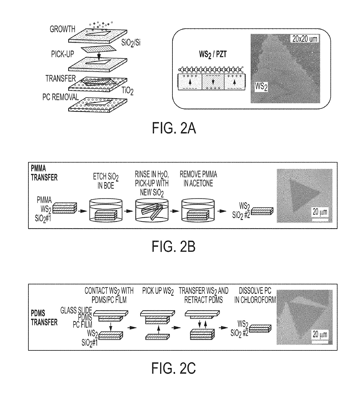
[0049]One method for mechanically transferring a TMD monolayer, such as WS2, onto a substrate, such as a ferroelectric film, includes the use of a PMMA film, as illustrated in FIG. 2B. A sample including a layer of WS2 on an SiO2 substrate is coated with a thin layer of PMMA (polymethyl methacrylate) resist and cured on a hot plate at 100° C. for 10 minutes, then submerged in buffered hydrofluoric acid to etch the SiO2, freeing the WS2 from the growth substrate. Once fully etched, the film was rinsed in deionized H2O, where it floated on the surface, and was then lifted from the water using the desired substrate. Optionally, adhesion of the WS2 layer may be improved by spinning at 2000 rpm and baking at 100° C. An acetone and isopropanol soak removes the PMMA. An optical image of PMMA transferred WS2 exhibits a uniform, clean, triangular shape, and is also shown in FIG. 2B.

example 2

[0050]Another method for mechanically transferring a TMD monolayer, such as WS2, onto a substrate, such as a ferroelectric film, includes the use of a PDMS / PC film, as illustrated in FIG. 2C. A sample including a layer of WS2 on an SiO2 substrate is brought into contact a PDMS / PC film, then retracted. This moves the WS2 from Si / SiO2 onto the PDMS / PC film. The PDMS / PC / WS2 stack is then placed onto clean Si / SiO2. The PDMS stamp is retracted, leaving the PC film on the top surface of WS2, which is then dissolved in chloroform. An optical image following PDMS transfer is shown in FIG. 2C.

example 3

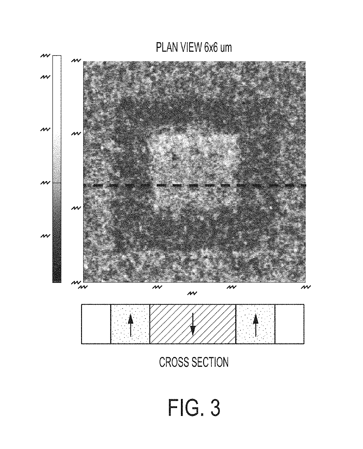
[0051]Polarization domains were written into a 150 nm PZT / Pt / SiO2 / Si test sample using a conductive atomic force microscope (CAFM) manufactured by Park Systems (Suwon, South Korea), in order to demonstrate that polarization domains in the ferroelectric film control photoluminescence (PL) intensity of mechanically transferred WS2 monolayers. The sample is shown in FIG. 3

[0052]The 6×6 micron image shown in FIG. 3 was obtained using the AFM operating in electric force microscopy imaging mode. The dark regions of the image correspond to the areas of the sample in which the AFM created dipole domains pointing up. The light regions of the image correspond to the areas of the sample in which the AFM created dipole domains pointing down. This is shown schematically in the accompanying cross section corresponding to the fiducial line drawn through the image. While the dipole domains shown here are about 500 nm in lateral dimension, domains on the scale of a few nanometers can also be success...


PUM

PropertyMeasurementUnit
thicknessaaaaaaaaaa
bias voltageaaaaaaaaaa

Abstract

The invention relates to heterostructures including a layer of a two-dimensional material placed on a multiferroic layer. An ordered array of differing polarization domains and surface charges in the multiferroic layer produces corresponding domains having differing properties in the two-dimensional material. When the multiferroic layer is ferroelectric, the ferroelectric polarization domains in the layer produce local electric fields that penetrate the two-dimensional material. The local electric fields and surface charges can control the structural phase of the two-dimensional material, which in turn determines whether the two-dimensional material layer is insulating or metallic, has a band gap or no band gap, and whether it is magnetic or non-magnetic. Methods for producing the heterostructures are provided. Devices incorporating the heterostructures are also provided.

Description

CROSS-REFERENCE TO RELATED APPLICATIONS[0001]This application claims priority to U.S. Provisional Application No. 62 / 424,711, filed on Nov. 21, 2016, U.S. Provisional Application No. 62 / 424,722, filed on Nov. 21, 2016, and U.S. Provisional Application No. 62 / 577,345, filed on Oct. 26, 2017, the contents of which are incorporated herein by reference in their entirety.TECHNICAL FIELD[0002]This application relates generally to heterostructures including a layer of a two-dimensional material placed on a multiferroic layer. An ordered array of differing polarization domains and surface charges in the multiferroic layer produces corresponding domains having differing properties in the two-dimensional material. When the multiferroic layer is ferroelectric, the ferroelectric polarization domains in the layer produce local electric fields that penetrate the two-dimensional material. The local electric fields and surface charges can control the structural phase of the two-dimensional material...

Claims


Application Information

Patent Timeline
Patent Type & Authority Patents(United States)
IPC IPC(8): H01L29/78H01L43/08H01L29/70G11C13/00G11C11/14H01L29/51G11C11/02G11C11/56H01L29/68H01L29/66G11C11/22H01L29/24H01L29/861H01F10/193H01L43/10H01L29/739H01L31/032G01R33/09H01L29/735
CPCG11C11/02H01L29/516H01L29/6684H01L29/685H01L29/70H01L29/735H01L29/7391H01L29/861H01L31/0322G01R33/09H01F10/1933G11C11/14G11C11/5678G11C13/0009H01L43/08H01L43/10H01L29/24H01L29/78391G11C11/223G01N27/4141Y02E10/541H10N50/10H10N50/85
Inventor JONKER, BEREND T.LI, CONNIE H.MCCREARY, KATHLEEN M.
Owner UNITED STATES OF AMERICA
Why Eureka
Try Eureka