Modular system for transporting wind turbine blades

a technology of wind turbine blades and modules, applied in the direction of load securing, machine/engine, load accommodation, etc., can solve the problem of potentially more turbulent sea transpor

Active Publication Date: 2019-10-01
LM WP PATENT HLDG
View PDF11 Cites 1 Cited by
  • Summary
  • Abstract
  • Description
  • Claims
  • Application Information

AI Technical Summary

Benefits of technology

[0014]It has been found that such modular system is inexpensive and offers a high degree of flexibility allowing for transport of two or more wind turbine blades in various spatial arrangements. For example, land transport in a stacked root end to tip end arrangement may be carried out with a minimum inter-blade spacing to minimise height of the overall stack by using the root end transport frames together with a set of first tip end transport frames having a height h1. When the freight is reloaded for subsequent sea transport a stacked root end to tip end arrangement with an increased inter-blade spacing and an increased overall stack height may be accomplished by replacing the first tip end transport frames with the second tip end frames of part (i) having a height h2 which exceeds h1. Reducing overall height is not as much of a concern in sea transport as compared to road transport. Instead, sea transport is potentially more turbulent which necessitates higher inter-blade spacings. A similar effect is obtained when using the tip end distance pieces of part (ii).
[0136]Supporting the tip portion of the wind turbine blade at such a location in the outboard portion of the blade, spaced from the tip end, provides a balance between effectively structurally supporting the blade, while reducing the minimum effective wheelbase or support surface needed to support the total transport system.

Problems solved by technology

Instead, sea transport is potentially more turbulent which necessitates higher inter-blade spacings.

Method used


Image

  • Modular system for transporting wind turbine blades
  • Modular system for transporting wind turbine blades
  • Modular system for transporting wind turbine blades

Examples


Embodiment Construction

[0138]The invention is explained in detail below with reference to embodiments shown in the drawings, in which

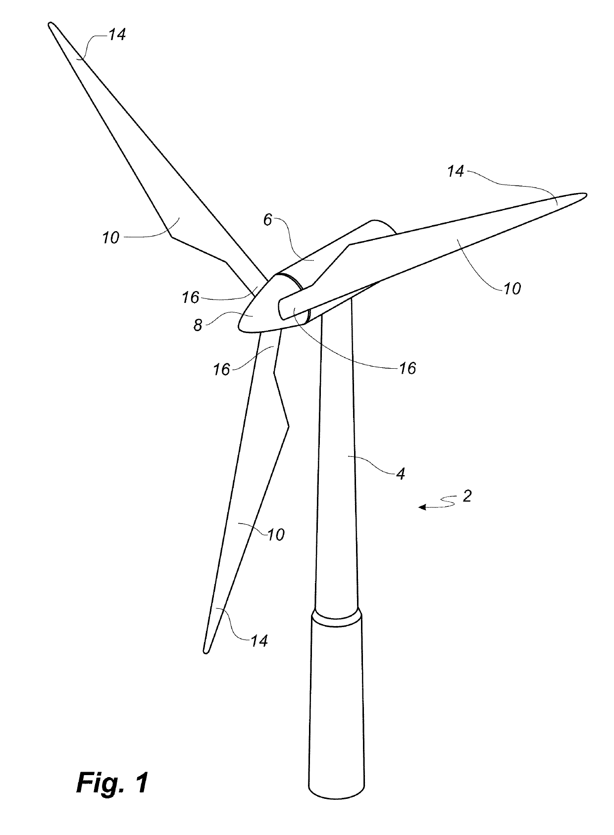
[0139]FIG. 1 shows a wind turbine,

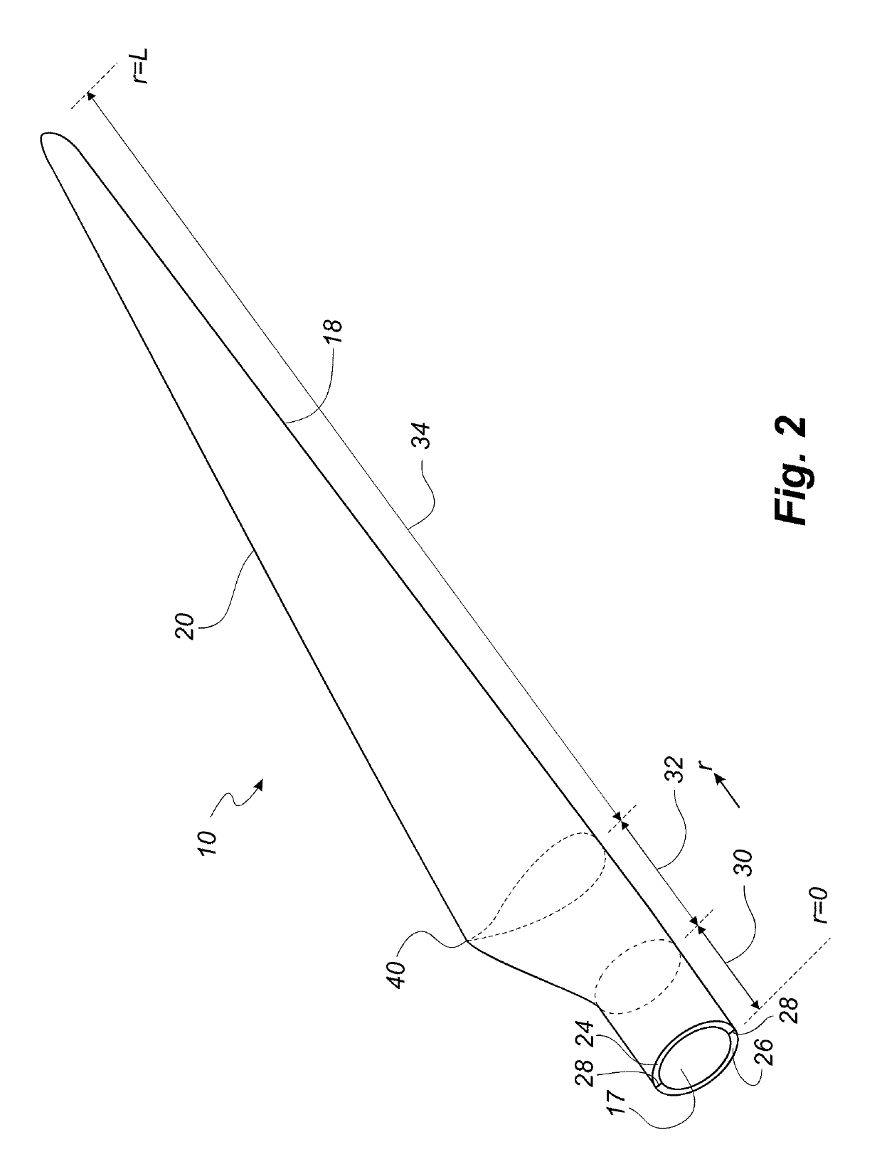
[0140]FIG. 2 shows a schematic view of a wind turbine blade according to the invention,

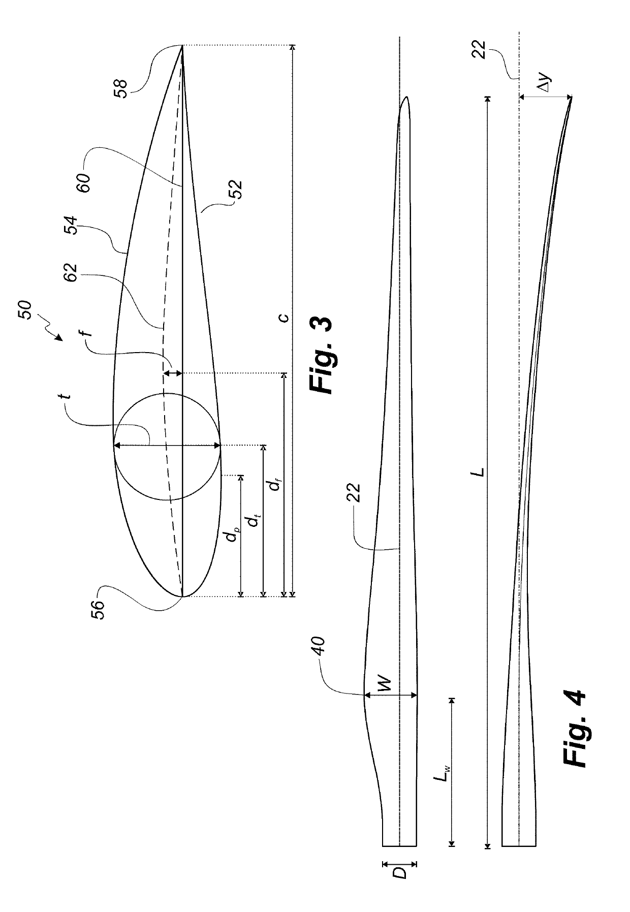
[0141]FIG. 3 shows a schematic view of an airfoil profile,

[0142]FIG. 4 shows a schematic view of the wind turbine blade according to an embodiment of the invention, seen from above and from the side,

[0143]FIG. 5 shows an embodiment of a root end transport frame according to an embodiment of the invention,

[0144]FIG. 6 shows an embodiment of a tip end transport frame according to an embodiment of the invention,

[0145]FIG. 7 shows a side view of an arrangement of wind turbine blades supported by one embodiment of a modular system according to the invention,

[0146]FIG. 8 shows a side view of an arrangement of wind turbine blades supported by another embodiment of a modular system according to the invention,

[0147]FIG. 9 shows a side view of an arrangement of wind...


PUM


Abstract

A modular system for transporting wind turbine blades in at least two different spatial arrangements comprising two or more root end transport frames having a height H for supporting the root end, wherein H<D (D=bolt circle diameter), and two or more first tip end transport frames having a height H1 for supporting the blade towards the tip end, each first tip end transport frame has a base frame and a support bracket provided on top of the base frame, wherein each first tip end transport frame is stackable on top of a root end transport frame and vice versa, so the system is operable to stack successive blades in an alternating root end to tip end arrangement. The first tip end transport frame is replaceable with a second end transport frame that increase the inter-blade spacing, or with a tip end or a root end distance piece.

Description

[0001]This is a National Phase Application filed under 35 U.S.C. 371 as a national stage of PCT / EP2014 / 065405, filed Jul. 17, 2014, the content of which is hereby incorporated by reference in its entirety.FIELD OF THE INVENTION[0002]The present invention relates to a modular system for transporting wind turbine blades and to a use of the system for providing a suitable spatial arrangement of at least two wind turbine blades for transport. The present invention also relates to a transport system for transporting wind turbine blades in at least two different spatial arrangements.BACKGROUND OF THE INVENTION[0003]Wind turbine blades used for horizontal axis wind turbines for generating electrical power from wind can be rather large and may exceed 70 meters in length and 4 meters in width. The blades are typically made from a fibre-reinforced polymer material and comprise an upwind shell part and a downwind shell part. Due to the size and fragility of these large rotor blades, the blades...

Claims


Application Information

Patent Timeline
Patent Type & Authority Patents(United States)
IPC IPC(8): B60P3/40B61D45/00B60P7/12B63B25/28B61D3/16B63B25/00B61D3/20B65D88/12B64D9/00B65D90/00F03D1/06F03D13/40
CPCF03D1/0675B61D45/007B63B25/28B63B25/004B60P3/40F03D13/40B60P7/12B61D45/00B65D88/12B61D3/20F03D1/0608B61D3/16B61D45/001B64D9/003B65D88/121B65D90/0073B63B25/00B61D45/003F05B2260/02Y02E10/721Y02E10/72
Inventor VAN DER ZEE, JACOBUS J
Owner LM WP PATENT HLDG
Why Eureka
Try Eureka