Stacked type falling film evaporator, zero liquid discharge system comprising the same, and zero liquid discharging method using the same

a technology of falling film evaporator and zero liquid discharge system, which is applied in the direction of evaporation, water treatment multi-stage treatment, separation process, etc., can solve the problems of increasing the supply price of industrial water, requiring a great deal of high-quality water, and increasing the production cost. , to achieve the effect of reducing the required site area, reducing energy consumption, and improving workability

Active Publication Date: 2019-10-22
DOOSAN HEAVY IND & CONSTR CO LTD
View PDF14 Cites 2 Cited by
  • Summary
  • Abstract
  • Description
  • Claims
  • Application Information

AI Technical Summary

Benefits of technology

[0022]Accordingly, the present disclosure has been made to address the above-mentioned problems. It is an object of the present disclosure to provide a stacked type falling film evaporator, a zero liquid discharge system comprising the same, and a zero liquid discharging method using the same. Two evaporators may respectively have evaporation tubes with a relatively short length that are installed in a two-stage stacked type in a vertical direction, thereby addressing the problems of other evaporators with reduced efficiency due to formation of a dry zone inside the evaporation tubes, providing easy installation and maintenance due to modularization, simplifying pipelines, and reducing a site area required for installing equipment.
[0031]The stacked type falling film evaporator, the zero liquid discharge system comprising the same, and the zero liquid discharging method using the same according to the embodiments of the present disclosure may enhance workability in installation and maintenance and may arrive at steady-state operating conditions because the evaporation tubes are shorter than the long tubes mounted in other falling film evaporators.
[0032]Additionally, the stacked type falling film evaporator, the zero liquid discharge system comprising the same, and the zero liquid discharging method using the same according to the embodiments of the present disclosure may address problems in installation and maintenance due to modularization of the stacked type system units, reduce required site area because the falling film evaporator is the stacked type, reduce energy consumption for carrying out processes because the piping structure of the falling film evaporator is simpler than a horizontal type multi-stage evaporator and does not require additional energy consumption for supply of wastewater to the downstream side, and multilaterally cope with the problem of the heat exchange type evaporator by vertical tubes that scale is formed on the inner walls of the tubes.

Problems solved by technology

There are indications of a gradual increase of the supply price of industrial water, a gradual increase of production costs due to an increase of discharge fees by regulations on total quantity of effluent water, and a scheduled enactment of a recycling obligation of more than ⅓ of effluent discharge flow.
The zero liquid discharge systems in Japan are mainly installed in high valued added semiconductor factories but require a great deal of high quality water and have significant installation and operating expenses because the installation regions are limited to specific contaminant discharge areas, such as national parks.
The plant is located in a large-scale agricultural area, water supply from nearby areas of the Mojave Desert is not good, and the price of water is very high.
The waste heat steam heating type requires a large-scale infrastructure, a large installation scale and excessive installation costs.
A flame direct heating type provides a treatment effect like a simple evaporation type but has increased energy consumption.
But this type has several disadvantages including that the treatment result may be non-uniform dependent on conditions of the introduced wastewater, and that it is difficult to maintain and repair due to maintenance of the vacuum condition.
However, if the wastewater film is broken, scale may be formed on the inner walls of the tubes.
The falling film evaporator is difficult to employ when the wastewater includes lots of scale components.
Therefore, the falling film evaporator has several disadvantages in that an evaporative concentration efficiency of the entire device is reduced because a zone where the wastewater film is dried, namely a dry zone, is highly likely to be formed in the proximity of the downstream side, in that workability is deteriorated at the time of installation or maintenance, and in that it takes a relatively long time to achieve operational conditions because the tubes are long.

Method used


Image

  • Stacked type falling film evaporator, zero liquid discharge system comprising the same, and zero liquid discharging method using the same
  • Stacked type falling film evaporator, zero liquid discharge system comprising the same, and zero liquid discharging method using the same
  • Stacked type falling film evaporator, zero liquid discharge system comprising the same, and zero liquid discharging method using the same

Examples


Embodiment Construction

[0038]Reference will be now made in detail to the embodiments of the present disclosure with reference to the attached drawings. It will be understood that words or terms used in the specification and claims shall not be interpreted as the meaning defined in commonly used dictionaries. It will be further understood that the words or terms should be interpreted as having a meaning that is consistent with their meaning in the context of the relevant art and the technical idea of the disclosure.

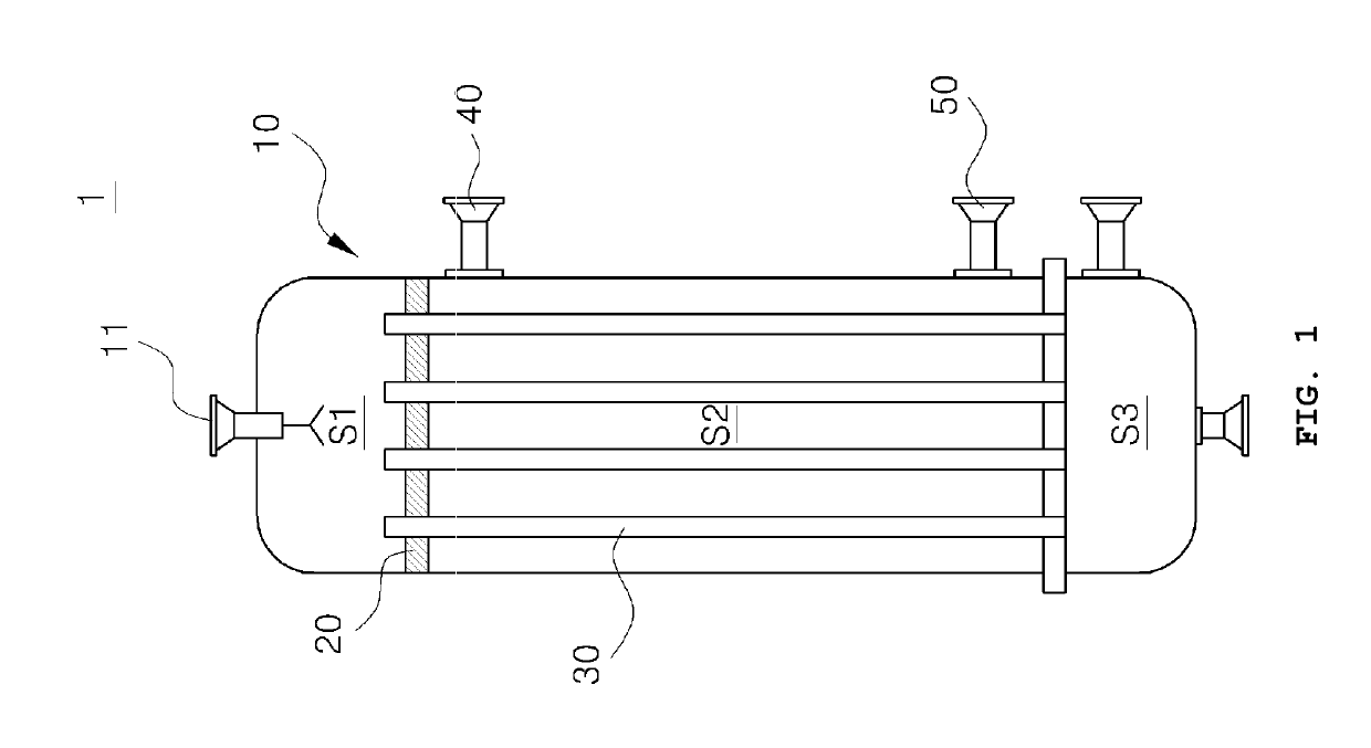
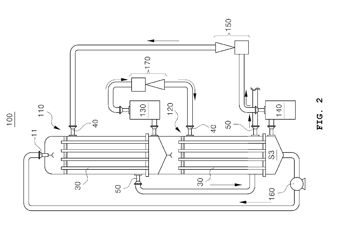
[0039]Referring to FIG. 2, according to an embodiment of the present disclosure, a stacked type falling film evaporator includes a first evaporator 110 and a second evaporator 120 respectively having evaporation tubes 30 of a length of 5 m to 10 m. The first evaporator 110 and the second evaporator 120 are stacked vertically in such a manner that wastewater passes through the first evaporator 110 and the second evaporator 120 in order. A first vapor recovering device 130 collects vapor generated...


PUM

PropertyMeasurementUnit
lengthaaaaaaaaaa
temperatureaaaaaaaaaa
lengthaaaaaaaaaa

Abstract

A stacked type falling film evaporator includes a first evaporator, a second evaporator, a first vapor recovering device, a second vapor recovering device and a vapor recompressor. The first evaporator and the second evaporator respectively have evaporation tubes of a length of 5 m to 10 m, and are stacked in such a manner that wastewater passes through the first evaporator and the second evaporator in order. The first vapor recovering device collects vapor generated from the wastewater in the first evaporator and supplies the collected vapor to the second evaporator. The second vapor recovering device collects vapor generated from the wastewater in the second evaporator and supplies the collected vapor to the first evaporator. The vapor recompressor compresses the vapor collected in the second vapor recovering device before the vapor is supplied to the first evaporator.

Description

CROSS-REFERENCE TO RELATED APPLICATIONS[0001]This application claims priority to Korean Application No. 10-2014-0002462, filed Jan. 8, 2014, the contents of which are incorporated herein in their entirety.BACKGROUND[0002]The present disclosure relates to a stacked type falling film evaporator, a zero liquid discharge system comprising the same, a zero liquid discharging method using the same. In particular, two evaporators may respectively have evaporation tubes with a relatively short length that are installed in a two-stage stacked type evaporator in a vertical direction, thereby addressing the problems of evaporators with reduced efficiency due to formation of a dry zone inside the evaporation tubes, providing easy installation and maintenance due to modularization, simplifying pipelines, and reducing a site area required for installing equipment.[0003]The stacked type falling film evaporator may be applied to a zero liquid discharge system for desulfurized wastewater in power pl...

Claims


Application Information

Patent Timeline
Patent Type & Authority Patents(United States)
IPC IPC(8): B01D1/06B01D3/00B01D1/28B01D21/01C02F1/04C02F1/08B01D9/00C02F1/52C02F1/44C02F11/127
CPCB01D21/01B01D1/065B01D1/2884C02F1/041B01D9/0031B01D3/007C02F1/08C02F11/127C02F1/441C02F2201/002C02F1/5245C02F2301/046C02F2001/5218C02F2301/08
Inventor KIM, SANG MOONRO, YOUNGJUNLEE, GUN MYUNGCHOI, JAE SEUNG
Owner DOOSAN HEAVY IND & CONSTR CO LTD
Why Eureka
Try Eureka