
Vehicle air conditioner system

a technology for air conditioner systems and vehicles, applied in indirect heat exchangers, light and heating equipment, laminated elements, etc., can solve the problems of increasing production costs, reducing the performance and efficiency of air conditioner systems for vehicles, and reducing the weldability of bonding parts, so as to reduce the production cost, reduce the package, and reduce the pipe configuration

Active Publication Date: 2019-10-22
HANON SYST
View PDF30 Cites 6 Cited by
  • Summary
  • Abstract
  • Description
  • Claims
  • Application Information

AI Technical Summary

Benefits of technology

This configuration reduces production costs, simplifies pipe connections, and enhances heat exchange efficiency by minimizing pressure drops and improving cooling performance.

Problems solved by technology

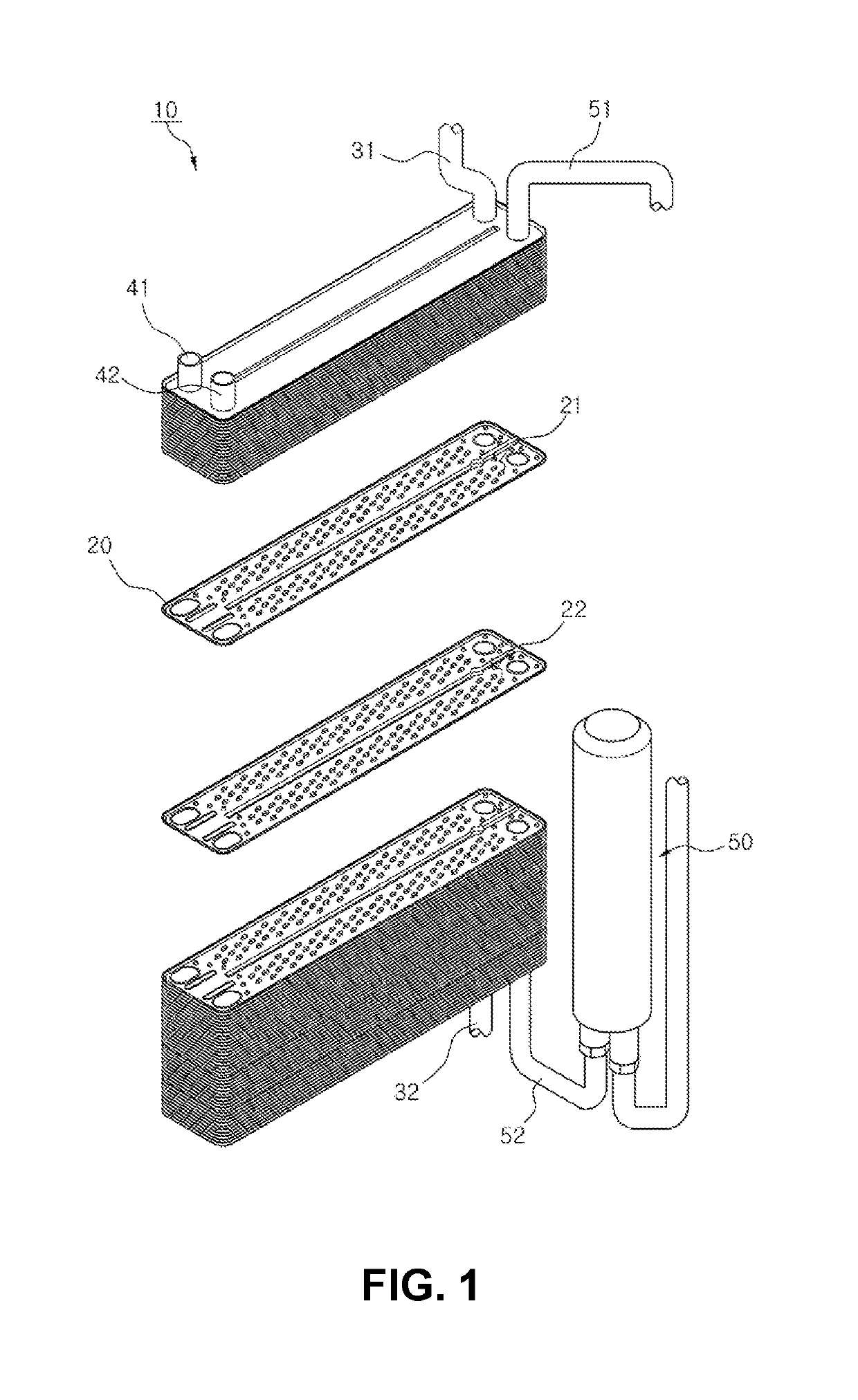
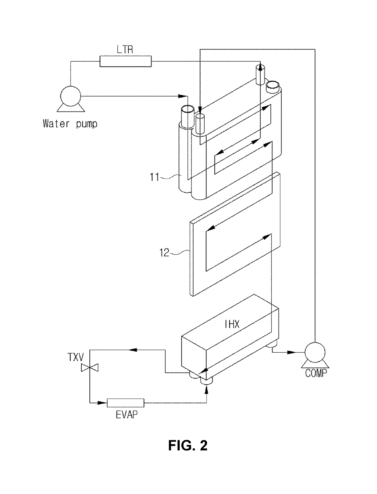
As illustrated in FIG. 2, in the case in which both of the water cooling condenser 11 and the air cooling condenser 12 are used, in the refrigeration cycle for a vehicle, a pipe layout becomes complicated in order to connect different types of heat exchangers to each other, and pipes should be additionally configured and assembled, and thus, an increase in a production cost is caused.
In addition, when the pipe layout becomes long and complicated, a refrigerant acts to be disadvantageous to a pressure drop while being moved, such that performance and efficiency of an air conditioner system for a vehicle cannot but be decreased.
However, there are problems that a tank of the sub-radiator and headers of the water cooling and air cooling condensers are different from each other, and an assembling property between the sub-radiator and the water cooling and air cooling condensers or weldability of a bonding part between the sub-radiator and the water cooling and air cooling condensers is low, and there is a limitation in improving all of the problems as described above.

Method used


Image

  • Vehicle air conditioner system
  • Vehicle air conditioner system
  • Vehicle air conditioner system

Examples


Embodiment Construction

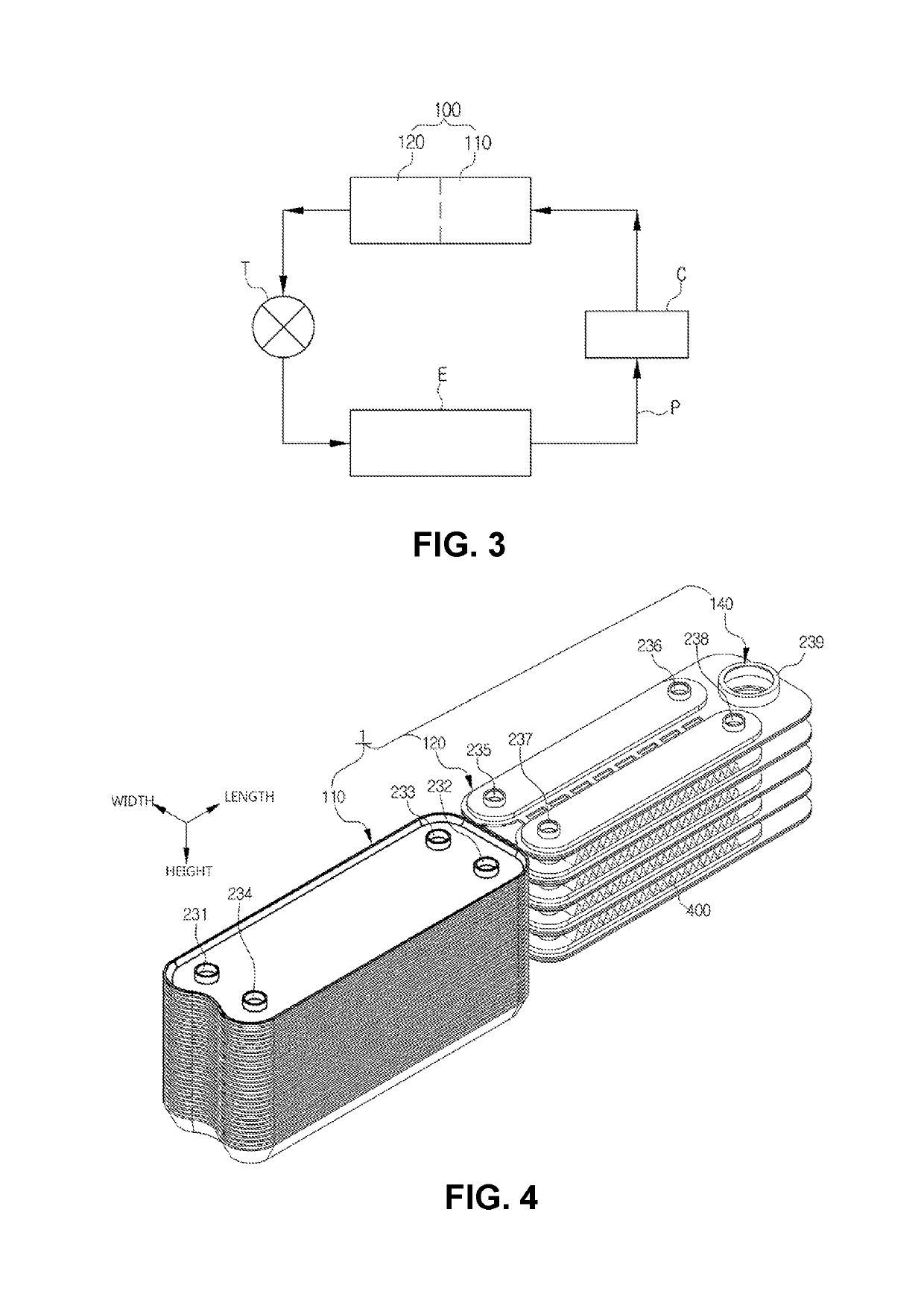
of Main Elements]C: compressorT: expansion valveE: evaporatorI: auxiliary heat exchangerP: refrigerant pipeA1: condensing regionA2: excessive cooling region100: integral condenser110: refrigerant channel part for water cooling condenser120: refrigerant channel part for air cooling condenser140: gas-liquid separator200: refrigerant plate201: first upper plate202: first lower plate211: first refrigerant inlet212: first refrigerant outlet221: second refrigerant inlet222: second refrigerant outlet231~239: first to ninth communication holes245~248: fifth to eighth communication channel parts251~254: first to fourth bonding parts255: division part256: partition part260: first flow part270: second flow part300: coolant plate301: second upper plate302: second lower plate311: coolant inlet312: coolant outlet400: heat radiation fin510~530: first to third connection parts600: flow pipe


PUM


Abstract

Provided is an air conditioner system for a vehicle. The air conditioner system for a vehicle includes a compressor, an integral condenser in which a water cooling region and an air cooling region are formed integrally with each other, an expansion valve, and an evaporator, wherein the water cooling region and the air cooling region of the integral condenser are formed on one plate, such that existing air cooling and water cooling condensers may be formed integrally with each other through one-time brazing coupling, thereby reducing a package and simplifying assembling and manufacturing processes.

Description

CROSS-REFERENCE TO RELATED APPLICATIONS[0001]This application is a United States national phase patent application based on PCT / KR2015 / 007622 filed Jul. 22, 2015, which claims the benefit of Korean Patent Application No. 10-2014-0093747 filed Jul. 24, 2014 and Korean Patent Application No. 10-2014-0093770 filed Jul. 24, 2014. The disclosures of the above patent applications are hereby incorporated herein by reference in their entirety.TECHNICAL FIELD[0002]The present invention relates to an air conditioner system for a vehicle, and more particularly, to an air conditioner system for a vehicle including a compressor, an integral condenser in which a water cooling region and an air cooling region are formed integrally with each other, an expansion valve, and an evaporator, wherein the water cooling region and the air cooling region of the integral condenser are formed on one plate, such that existing air cooling and water cooling condensers may be formed integrally with each other thr...

Claims


Application Information

Patent Timeline
Patent Type & Authority Patents(United States)
IPC IPC(8): B60H1/00F28F3/08F28F3/02F28D9/00F25B1/00B60H1/32F25B39/04F28D21/00
CPCB60H1/00335B60H1/00342F28F3/086B60H1/3227F25B1/00F25B39/04F28F3/025F28D9/0043F28D9/0093F28D2021/0084F25B2339/043F25B2339/047F25B2500/18F28D1/0461F28D1/0341F28D1/0333F28D9/005
Inventor LEE, HAE-JUNLEE, SANGMINAHN, YONG NAMCHOI, JUN YOUNG
Owner HANON SYST
Learn More