
Indicating devices based on lateral diffusion of a mobile phase through a non-porous stationary phase

a technology of mobile phase and indicating device, which is applied in the direction of instruments, horology, analysis using chemical indicators, etc., can solve the problems of failure in practice, devices that have not been completely satisfactory, and microwave ovens that do not heat food uniformly, etc., to increase the rate of diffusion of mp, increase the effect of diffusion ra

Active Publication Date: 2019-10-22
JP LAB INC
View PDF25 Cites 10 Cited by
  • Summary
  • Abstract
  • Description
  • Claims
  • Application Information

AI Technical Summary

Benefits of technology

The invention is an indicating device that produces a noticeable or measurable change based on the lateral diffusion of a mobile phase through a layer of non-porous stationary phase. The mobile phase is a solid, liquid, or gas that can react with an activator or indicator to produce a color or fluorescence. The device can be made by coating the mobile phase onto a substrate or sandwiching it between two layers. The device can also contain a controller to control its properties and performance. The invention can be used in various applications such as indicating the presence or absence of a specific substance or condition. The device can be printed on a surface or embedded in a substrate. The invention has a fast activation time, high sensitivity, and low activation energy. The device can also have a long service life and can be used in various forms such as a tape or a circular.

Problems solved by technology

For example, a TTI device might indicate exposure to an excessive temperature for an excessive period of time or both.
A microwave oven does not heat the food uniformly.
This type of indicating devices undergo a color change with time and temperature when the product temperature undesirably exceeded above a pre-determined temperature, e.g., about 0° C. These devices have not proven entirely satisfactory due either to deficiencies in their visual perceptual character or in the danger of their use, in their sensitivity to thawing conditions or in their complexity of manufacture or use.
The shortcomings of such devices are that they often fail in practice.
Direct testing for sterility is destructive and expensive and hence indirect testing methods, such as color changing indicating devices are used.
In either case the dye is visible through the polymeric layers, with the dye being positioned directly below the valve member, however, so that the valve member at least partially obstructs visibility of the dye deposit.
The known devices are difficult to make as a special construction of the liquid reservoir is required and devices require sealing, usually heat sealed at the edges to control the movement of the liquid.
It is also difficult to make small, e.g., smaller than a centimeter devices.

Method used

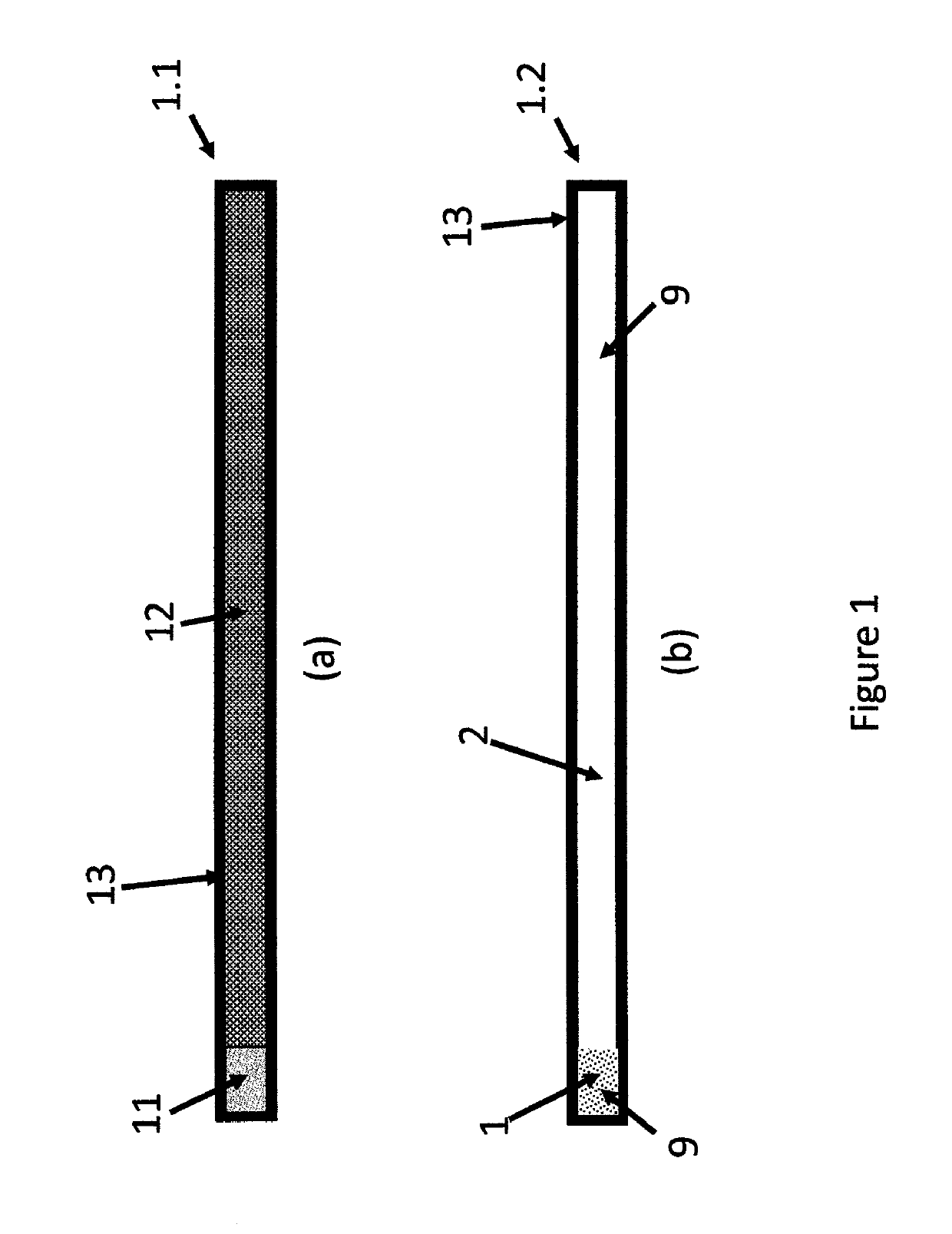
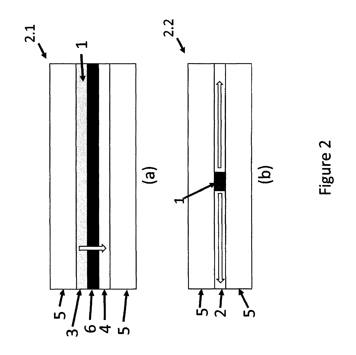
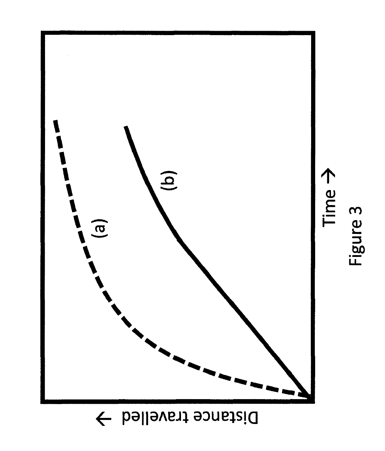

Image

  • Indicating devices based on lateral diffusion of a mobile phase through a non-porous stationary phase
  • Indicating devices based on lateral diffusion of a mobile phase through a non-porous stationary phase
  • Indicating devices based on lateral diffusion of a mobile phase through a non-porous stationary phase

Examples


example 1

nd Comparison Experiments of Known Art and Current Invention with a Fluid MP and a Solid MP

[0400]In order to obtain a solid MP on SP, 0.1 g of methyl yellow was dissolved in 0.25 g of THF, a volatile solvent. In order to get liquid or semi-solid MP, 0.1 g of methyl yellow was dissolved in 0.25 g of benzyl ether, a non-volatile solvent. A drop each of these two solutions was placed on three SP (i) cellulose / copying paper as a porous SP, (ii) a polyester film coated 50 microns of S85 PSA without any accelerator and (iii) a polyester film coated with 50 microns of S85 PSA containing 50% bis(2-ethylhexyl sebacate) as shown in FIGS. 13(a1), 13(a2) and 13(a3). S85 is a pressure sensitive solvent based acrylic adhesive supplied by Avery Dennison, Painesville, Ohio. THF being highly volatile solvent (boiling point 66° C.), it evaporated within minutes at room temperature and spots of dry powder of the dye ware obtained. The spots of benzyl ether remained wet as it is a high boiling (boiling...

example 2

a SP

[0410]A large number of dyes were dissolved in proper solvents and spotted on 50 micron thick layer of S85 on 40 micron polyester film, let the solvents evaporate, laminated with another 40 micron polyester film and stored in an over at about 80° C. Colored spots of many dyes grew at different speeds depending upon the nature of the dyes. Ionic dyes either did not grow or grew very slowly. The spots of dyes with lower molecular weight, such as methyl yellow usually grew rapidly. Dyes with moderate molecular weight, such as Sudan II grew slowly while dyes with very high molecular weight grew very slowly or did not grow.

[0411]In order to study effect of time on migration of the boundary, 0.1 g methyl yellow was dissolved in 0.25 g of THF. Drops of the solution were placed on a 40 micron polyester film coated with 50 micron thick layer of S85. THF evaporated within minutes at room temperature and spots of dry powder of the dye ware obtained. The coating was laminated with a clear p...

example 3

Adhesive as a SP

[0412]We discovered that it is not necessary to have a PSA as SP for the devices of this invention. A number of hot melt, non-tacky polyurethane and acrylic hot melt adhesives coated on polyester films were obtained from different distributors and manufacturers. Dry spots of methyl yellow and Sudan II in THF were prepared on the hot melt adhesive and laminated either with a clear polyester film or with the same hot melt adhesive film using a heat laminator between 110° C. and 150° C. depending upon the nature of the hot melt adhesive. The samples were annealed at different temperatures. FIG. 14(b) shows different stages of growth of the Sudan II on a 25 micron thick layer of an acrylic hot melt adhesive (a polyester film coated with an acrylic hot melt adhesive supplied by Transilwrap, Bethlehem, Pa.) with time at 60° C. When the SP is an acrylic hot melt adhesive the growth of the spot was lower than that of PSA.

[0413]In another experiment, a 25 micron polyethylene ...


PUM

PropertyMeasurementUnit
temperatureaaaaaaaaaa
pore sizeaaaaaaaaaa
activation energyaaaaaaaaaa

Abstract

This invention relates to indicating devices, such as time-temperature indicators based on lateral diffusion of a vapor of a solid and / or liquid mobile phase (e.g., a sublimeable dye or an activator) through a non-porous stationary phase, such as a thin layer of a polymeric material. The lateral diffusion of the mobile phase creates a noticeable boundary in the stationary phase whose movement depends upon processes, such as time and temperature.

Description

[0001]This application claims the benefit of U.S. Provisional Applications No. 61 / 932,102, filed Jan. 27, 2014 and No. 62 / 022,907 filed Jul. 10, 2014.[0002]The present invention relates to an indicating device such as a time, temperature, time-temperature, food doneness, thaw and sterilization indicator based on lateral diffusion of a mobile phase through a non-porous stationary phase, such as a thin layer of a polymeric material. The lateral diffusion of the mobile phase creates a boundary whose movement depends upon processes, such as time and temperature.BACKGROUND OF THE INVENTION[0003]Perishable products have measurable shelf-lives, which are usually expressed within specified limits as the time left for available end use. The term “perishable(s)” or “perishable product(s)” is meant herein to include perishable foods, such as fresh, refrigerated, and frozen, vegetables, fruits, meats, fish, poultry, dairy products, bakery products, juices, pre-cooked foods, soft and alcoholic b...

Claims


Application Information

Patent Timeline
Patent Type & Authority Patents(United States)
IPC IPC(8): G01K3/04G07C1/00G01N31/22G04F1/00
CPCG01K3/04G04F1/00G07C1/00G01N31/229G01N31/22
Inventor PATEL, GORDHANBHAI NKOLEDA, JULIA
Owner JP LAB INC
Learn More