Machine learning based post route path delay estimator from synthesis netlist

a technology of post route path delay and estimator, which is applied in the field of machine learning based post route path delay estimator from synthesis netlist, can solve the problems of backend flow, different wire load between post route routes, and long completion time (days)

Active Publication Date: 2019-11-26
NVIDIA CORP
View PDF4 Cites 1 Cited by
  • Summary
  • Abstract
  • Description
  • Claims
  • Application Information

AI Technical Summary

Benefits of technology

[0005]The method is data driven instead of algorithm driven. The prediction model is fit from the real design output generated by the backend tools, without knowledge of the backend algorithm details. At inference time, the prediction model executes efficiently, and does not add significantly to the synthesis runtime. Fast and accurate path delay estimation helps improve the efficiency of, and reduce the time for, design space exploration based on the synthesis netlist. Efficient design space exploration enables identification of designs with better QoR, which enables the production of improved microchip products. Furthermore, the present system improves timing optimization in the backend flow and / or the engineering change order (ECO) flow that utilize the predicted path delay in their operations.

Problems solved by technology

However, the backend flow (described further below) may take a long time (days) to complete and, thus, evaluate a final post route QoR from the synthesis stage.
One challenge of predicting post route QoR, such as the path delay between two sequential points from the synthesis stage, is that the paths at the synthesis stage are not the same as those at the post route stage.
The large routing parasitic created by routing through congested regions may also make wire load different between the post route and the synthesis stages.
These issues create a problem for the design space exploration process because the timing analysis at the synthesis stage cannot accurately estimate the timing at the post route stage.
Another problem is that synthesis optimization based on its own timing analysis might not achieve the optimal results either, because it might work on the wrong critical paths.
However, these solutions are time consuming and do not provide an accurate prediction of all potential changes to the netlist in the backend flow.

Method used


Image

  • Machine learning based post route path delay estimator from synthesis netlist
  • Machine learning based post route path delay estimator from synthesis netlist
  • Machine learning based post route path delay estimator from synthesis netlist

Examples


Embodiment Construction

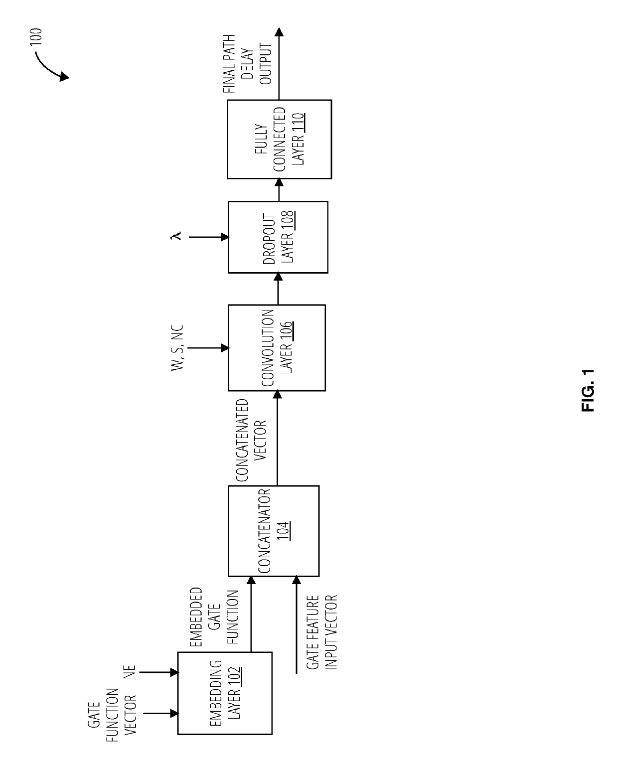
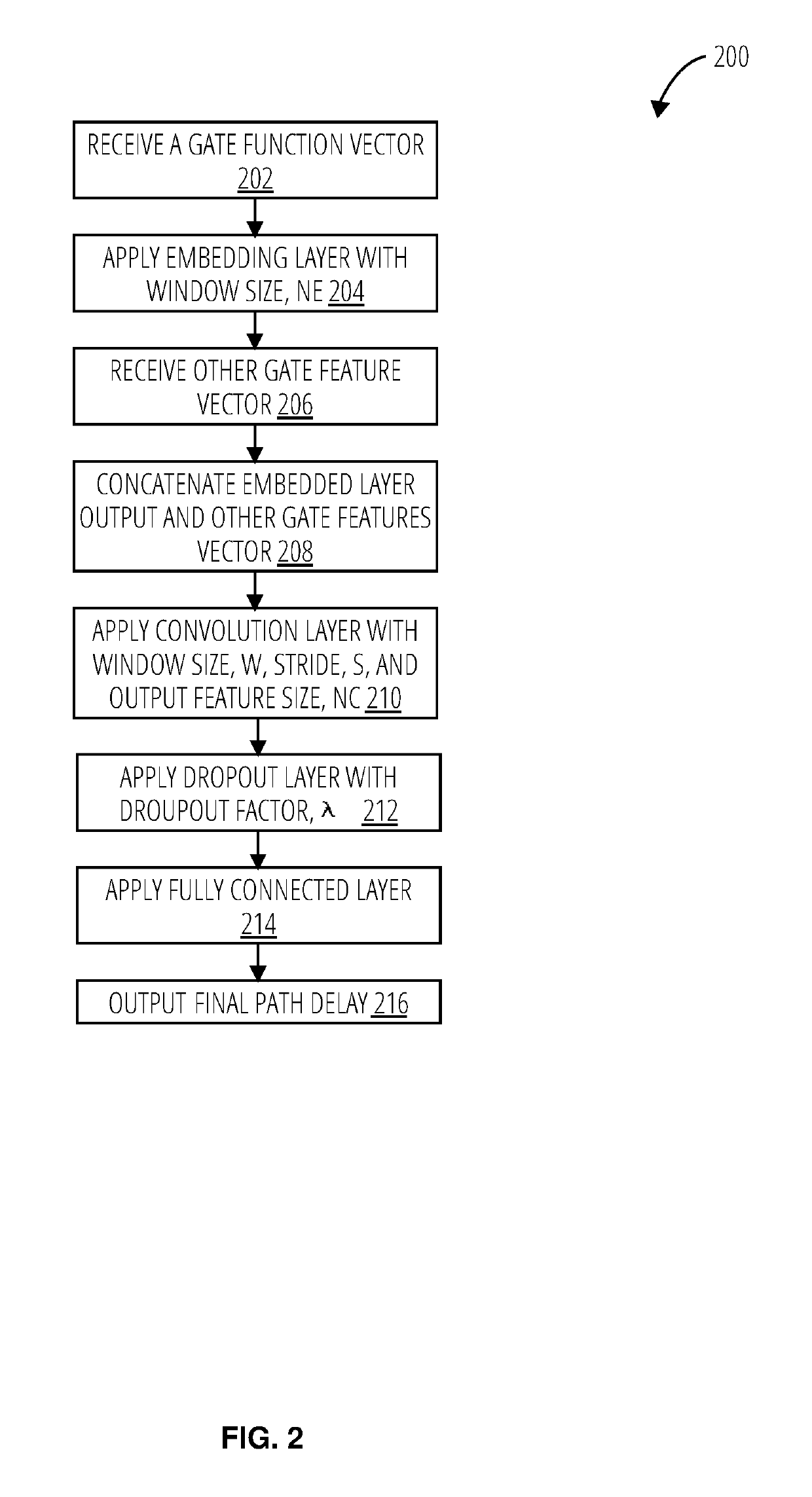
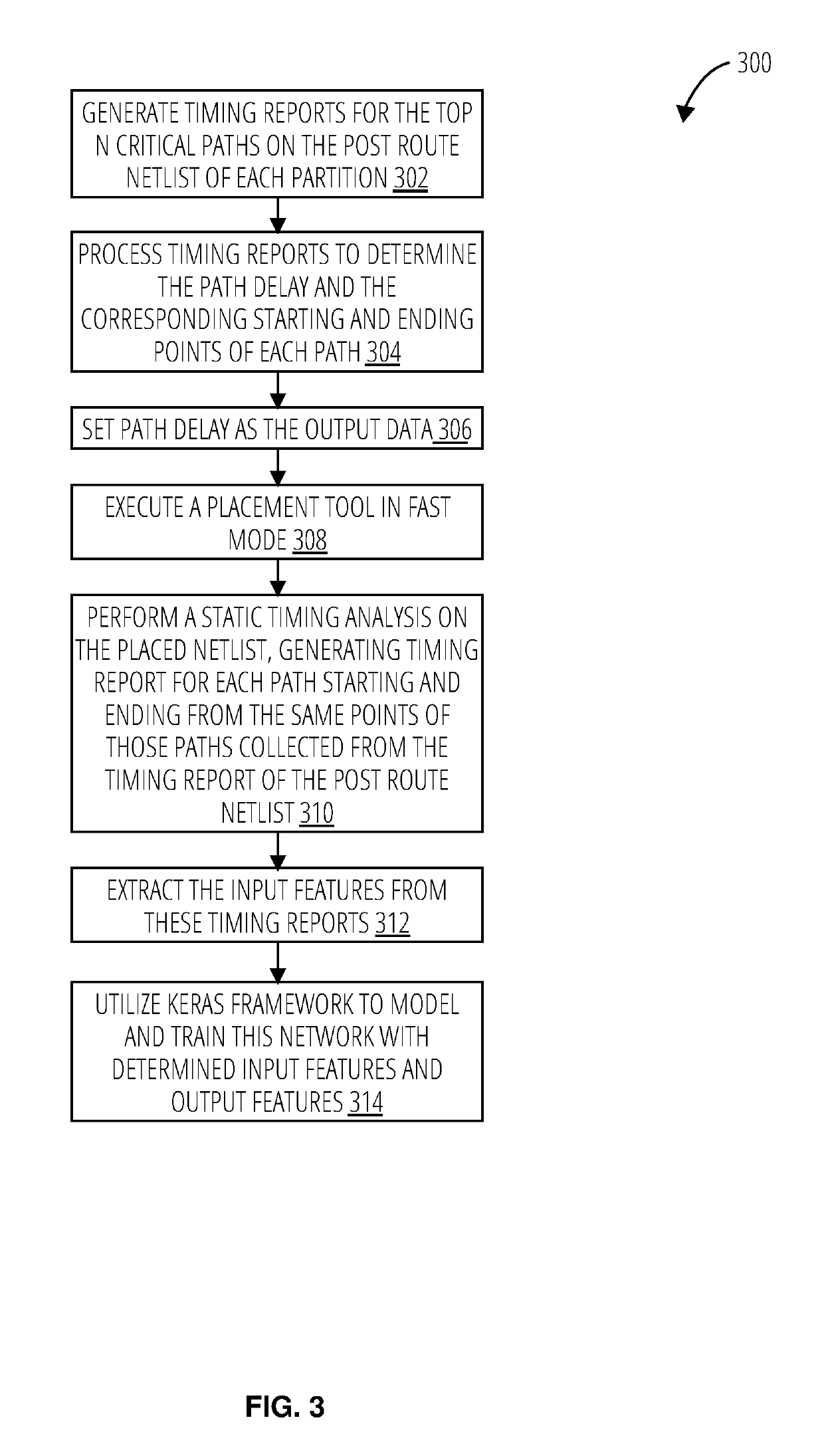
[0013]Disclosed herein are processes and systems that improve the efficiency of machines that generate control structures (e.g., post-route / placement netlist logic, maskworks) input by other machines to manufacture complex electronic circuitry. The processes and systems generate post-routing path delay readings faster and with more accuracy than conventional systems, and thus improve timing optimization in the control structures used by machines that manufacture microchip products. For example the control structures generated using the disclosed processes and systems may be utilized to generate post-route netlist logic that is transformed into maskworks which in turn operate photolithographic equipment that manufactures microchips. The disclosed processes and systems are thus improvements to the efficiency and computerization of the inherently technological process of manufacturing microchips and lead directly to faster and more efficient microchips.

[0014]A machine learning system i...


PUM


Abstract

A neural network including an embedding layer to receive a gate function vector and an embedding width and alter a shape of the gate function vector by the embedding width, a concatenator to receive a gate feature input vector and concatenate the gate feature input vector with the gate function vector altered by the embedding width, a convolution layer to receive a window size, stride, and output feature size and generate an output convolution vector with a shape based on a length of the gate function vector, the window size of the convolution layer, and the output feature size of the convolution layer, and a fully connected layer to reduce the gate output convolution vector to a final path delay output.

Description

BACKGROUND[0001]Very-large-scale integration (VLSI) design teams strive to build high ‘quality of result’ (QoR) products. One way to increase QoR is by exploring a large design space during the synthesis stage. However, the backend flow (described further below) may take a long time (days) to complete and, thus, evaluate a final post route QoR from the synthesis stage. Therefore, it is important to be able to predict QoR in the synthesis stage, or earlier stages of the backend flow.[0002]One challenge of predicting post route QoR, such as the path delay between two sequential points from the synthesis stage, is that the paths at the synthesis stage are not the same as those at the post route stage. The backend design flow may change these combinational paths. It may place all the gates and route all the nets. It may also add buffers, resize gates, and change the circuit structures. In the end, the combinational paths may be significantly different to those at the synthesis stage. Th...

Claims


Application Information

Patent Timeline
Patent Type & Authority Patents(United States)
IPC IPC(8): G06F17/50G06N3/08G06N3/04
CPCG06N3/04G06F17/505G06N3/08G06F30/327G06F2119/12G06N3/082G06N3/045
Inventor REN, MARKKHAILANY, BRUCEK
Owner NVIDIA CORP
Why Eureka
Try Eureka