Engine cooling configurations with waste heat recovery system

a technology of waste heat recovery and engine cooling, which is applied in the direction of steam engine plants, machines/engines, mechanical equipment, etc., can solve the problems of reducing the thermal efficiency of the whr system, and reducing the cooling efficiency of the engine, so as to maximize the power recovered, maximize the thermal efficiency of the whr system, and achieve the effect of good useability

Active Publication Date: 2019-12-03
INT ENGINE INTPROP CO LLC
View PDF13 Cites 1 Cited by
  • Summary
  • Abstract
  • Description
  • Claims
  • Application Information

AI Technical Summary

Benefits of technology

[0009]By using a WHR working fluid cooled engine coolant heat exchanger / boiler, embodiments of the engine cooling configurations with waste heat recovery system fully integrate the engine cooling system with the waste heat recovery system. In this way, the WHR working fluid condenser functions as the main heat rejection device in the system, in place of an engine coolant radiator. Therefore, the WHR working fluid condenser may be the only heat exchanger placed at or near the front of the vehicle in order to utilize ram air in a vehicular application, or that requires one or more cooling fans in other applications. This maintains a large temperature differential between the waste heat sources and the heat sink that is the WHR working fluid condenser, thereby maximizing the thermal efficiency of the WHR system. Furthermore, the use of a WHR working fluid cooled CAC in combination with the WHR working fluid cooled engine coolant heat exchanger / boiler eliminates the necessity for arranging multiple heat exchangers at or near the front of the vehicle, such as a conventional engine coolant radiator, a conventional CAC, and / or any additional WHR working fluid condenser as might be required if the engine cooling system were not fully integrated with the waste heat recovery system. The WHR working fluid condenser itself may be directly air cooled, or may be liquid cooled by way of an additional heat exchanger, according to the particular needs of the application.
[0015]Embodiments of the WHR system are able to extract as much usable work from waste heat as possible from sources including engine coolant, heat from compressed charge air, engine exhaust gas, exothermic and combustion reactions within aftertreatment devices, and EGR gas, at least in part by maintaining a large temperature differential between the waste heat sources and the heat sink that is the WHR working fluid condenser, thereby maximizing the thermal efficiency of the WHR system. Integration of the WHR system with the engine cooling system maximizes the power recovered by the WHR system, and therefore increases the overall engine brake thermal efficiency (BTE) and improves fuel economy. Embodiments of engine cooling configurations with a WHR system are capable of more efficient cooling of both the engine and the WHR system itself, since only the WHR condenser may be located in the front of the truck. This may result in less ram air restriction and better overall cooling of the system. It may further result in more flexible packaging of the heat exchangers and a more aerodynamic vehicle design. Embodiments of engine cooling configurations with a WHR system are adaptable for use with engines of various configurations using any of several thermodynamic cycles, as noted previously. The heat exchangers, boilers, and / or superheaters used in the WHR system may be readily configured using principles of engineering applicable to heat exchangers, boilers, and / or superheaters.

Problems solved by technology

Due to friction, normal heat losses, and inherent efficiency limitations, the use of such thermodynamic cycles to produce useful work results in the rejection of waste heat to the environment.
However, exhaust gas recirculation also hinders the thermodynamic efficiency of the engine.
The exothermic reactions or regeneration events utilized in these aftertreatment devices, therefore, further results in rejection of waste heat to the environment.

Method used


Image

  • Engine cooling configurations with waste heat recovery system
  • Engine cooling configurations with waste heat recovery system
  • Engine cooling configurations with waste heat recovery system

Examples


Embodiment Construction

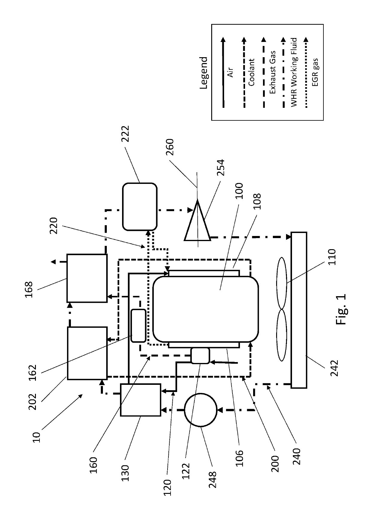
[0026]Referring now to FIG. 1, a graphical representation of an embodiment of an engine cooling configuration with a waste heat recovery (WHR) system 10 is shown. An engine 100 is provided for converting stored chemical energy in the form of fuel into usable work such as rotational torque and power used, for example, to propel a vehicle. The engine 100 has an engine charge air intake manifold 108 for distributing intake, or charge, air to the several cylinders of the engine 100. The engine 100 also has an engine exhaust manifold 106 for combining and discharging exhaust gas produced by the several cylinders of the engine 100. The engine 100 is further provided with a turbocharger 122 connected to the engine exhaust manifold 106 for compressing charge air to be delivered to the engine charge air intake manifold 108. One or more exhaust aftertreatment devices 162 are provided for reducing pollutants discharged with the exhaust gas.

[0027]An engine coolant circuit 200 circulates engine ...


PUM


Abstract

A vehicle has a waste heat recovery (WHR) system and an engine. The WHR system includes a WHR working fluid circuit with a pump, a power turbine, and a condenser. An engine coolant circuit circulates coolant between the engine and an engine coolant heat exchanger / working fluid boiler in the WHR working fluid circuit. At least one exhaust gas heat exchanger / superheater in the WHR working fluid circuit receives waste heat from an exhaust circuit and / or from an exhaust gas recirculation circuit. A working fluid cooled charge air cooler in the WHR working fluid circuit receives waste heat from compressed charge air in a charge air intake circuit. A recuperator may transfer waste heat from working fluid passing from the power turbine to the condenser to working fluid passing from the working fluid cooled charge air cooler to the engine coolant heat exchanger / working fluid boiler.

Description

BACKGROUNDField of Invention[0001]Embodiments described herein generally relate to a system and method for integrating engine cooling, charge air cooling, exhaust cooling, and exhaust gas recirculation cooling with a waste heat recovery system that uses a working fluid to recover usable energy from these sources of waste heat.Related Art[0002]A vehicle, such as a truck, a bus, and the like, is often provided with an engine that converts stored chemical energy in the form of fuel into usable work such as rotational torque and power used to propel the vehicle and to provide for other vehicle power needs. This conversion of chemical energy to usable work is commonly by way of one or more thermodynamic cycles, such as the Otto cycle or the diesel cycle, as non-limiting examples. Due to friction, normal heat losses, and inherent efficiency limitations, the use of such thermodynamic cycles to produce useful work results in the rejection of waste heat to the environment. This commonly take...

Claims


Application Information

Patent Timeline
Patent Type & Authority Patents(United States)
IPC IPC(8): F02G5/02F01K23/10
CPCF02G5/02F02G2260/00F01K23/10Y02T10/12
Inventor WU, SHOUHAOSIUCHTA, GRZEGORZOPPERMANN, DEAN
Owner INT ENGINE INTPROP CO LLC
Why Eureka
Try Eureka