Optical fiber sensing method

a technology of optical fiber and sensing method, which is applied in the direction of force measurement by measuring optical property variation, force/torque/work measurement apparatus, instruments, etc., can solve the problems of affecting the life and property of people, affecting the country's economy, and the inability to observe daily variation in real time, etc., to achieve easy maintenance, low cost, and easy on-site construction

Active Publication Date: 2019-12-03
NAT APPLIED RES LAB
View PDF11 Cites 0 Cited by
  • Summary
  • Abstract
  • Description
  • Claims
  • Application Information

AI Technical Summary

Benefits of technology

[0006]One objective of the present invention is to provide an optical fiber sensing method and device, which are advantageous of easy on-site construction, recyclability of components, changeability of design parameters, low cost, easy maintenance and long service life. The sensing method or device may be applied in monitoring the inclination or settlement of the environment or structures (such as buildings, bridges, roads) to instantly ensure the safety of the environment and the structures.
[0013]In the present invention, an additional fixing element may be further provided to be sleeved and fastened on the heat shrinkable tube at the upper end of the sensing segment. Additionally, the container can further include at least one covering plate for sealing the top opening of each accommodating portion and supporting the fixing element above the sensing segment so as to provide tensile force on the grating and reduce evaporation of the fluid. More specifically, the covering plate can have a trench to permit the optical fiber to vertically extend into the interior of the accommodating portion. In order to avoid displacement of the upper fixing element, the covering plate may further have a limiting structure that conforms to the four lateral sides of the upper fixing element so that the fixing element disposed across the trench of the covering plate can be confined at the predetermined location. Accordingly, the fixing element above the sensing segment can be fastened to the container through the covering plate, and the upper end of the sensing segment can be secured to the container through the fixing element and the covering plate.

Problems solved by technology

In recent years, disasters took place in many countries, which not only threaten people's life and properties but also may affect the country's economy.
Therefore, instantly monitoring the conditions about the environment and buildings and early warning become important issues to reduce the impact caused by disasters.
As the environment and the buildings were not monitored continuously, their daily variation cannot be observed in real time.
This causes that reinforcements or maintenance cannot be made appropriately and even early warnings cannot be issued before disasters.
However, many conventional sensing methods and devices have not been widely applied yet due to their disadvantages, such as difficulty in on-site construction, high cost, unchangeable system parameters, non-recyclability, or short service life.

Method used


Image

  • Optical fiber sensing method
  • Optical fiber sensing method
  • Optical fiber sensing method

Examples


Embodiment Construction

[0028]Hereafter, examples will be provided to illustrate the embodiments of the present invention. Advantages and effects of the invention will become more apparent from the disclosure of the present invention. It should be noted that these accompanying figures are simplified and illustrative. The quantity, shape and size of components shown in the figures may be modified according to practical conditions, and the arrangement of components may be more complex. Other various aspects also may be practiced or applied in the invention, and various modifications and variations can be made without departing from the spirit of the invention based on various concepts and applications.

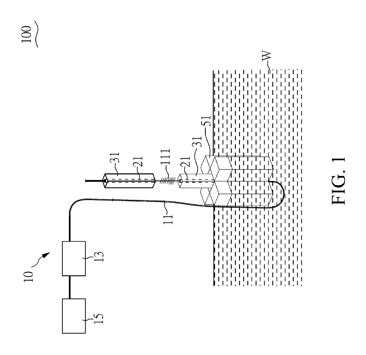
[0029]Please refer to FIG. 1, which shows a perspective view of an optical fiber sensing system 100 in accordance with one embodiment of the present invention. As illustrated in FIG. 1, the optical fiber sensing system 100 of this embodiment includes an optical fiber measuring unit 10, heat shrinkable tubes 21,...


PUM

PropertyMeasurementUnit
heat shrinkableaaaaaaaaaa
tensile forceaaaaaaaaaa
buoyant forceaaaaaaaaaa

Abstract

The optical fiber sensing method of the present invention includes steps of: joining heat shrinkable tubes to two ends of a sensing segment of an optical fiber; coupling a fixing element on the heat shrinkable tube below the sensing segment; detachably connecting at least one floating element to the fixing element; placing the floating element into a fluid; and providing an input signal to the sensing segment and generating an output signal after the input signal is processed by the sensing segment, wherein the tensile force applied to the sensing segment would change with variation of the buoyant force upon the floating element, resulting in change of the output signal. Accordingly, the optical fiber sensing method has numerous advantages, including rapid on-site construction, recyclability of components and changeability of design parameters.

Description

CROSS REFERENCE TO RELATED APPLICATION[0001]This application claims the benefits of the Taiwan Patent Application Serial Number 106131362, filed on Sep. 13, 2017, the subject matter of which is incorporated herein by reference.BACKGROUND OF THE INVENTION1. Field of the Invention[0002]The present invention relates to an optical fiber sensing method and, more particularly, to an optical fiber sensing method by which components are recyclable and parameters are alterable.2. Description of Related Art[0003]In recent years, disasters took place in many countries, which not only threaten people's life and properties but also may affect the country's economy. Therefore, instantly monitoring the conditions about the environment and buildings and early warning become important issues to reduce the impact caused by disasters. Particularly, by monitoring the conditions of environment and buildings before the disaster, appropriate emergency measures can be immediately taken so as to reduce life...

Claims


Application Information

Patent Timeline
Patent Type & Authority Patents(United States)
IPC IPC(8): G01L1/24G02B6/02G01L5/10
CPCG02B6/02076G01L5/105G01L1/246G01C5/04G01C9/22G01D5/35316G01M5/0008G01M5/005G01M11/083G01L5/0033G01B11/18
Inventor LEE, ZHENG-KUAN
Owner NAT APPLIED RES LAB
Why Eureka
Try Eureka