Synchronous rectification control circuit, method and flyback switch circuit

a control circuit and synchronous rectification technology, applied in the field of switching mode power supply technology, can solve the problems of high system efficiency, difficult to obtain the switching signal of the main switching tube, and difficulty in current synchronous rectification control of the synchronous rectification transistor, so as to improve the reliability of the system, accelerate the turn-off speed, and reduce the resistance to voltag

Active Publication Date: 2019-12-10
JOULWATT TECH INC LTD
View PDF1 Cites 9 Cited by
  • Summary
  • Abstract
  • Description
  • Claims
  • Application Information

AI Technical Summary

Benefits of technology

[0005]The present invention provides a synchronous rectification control circuit, a method, and a flyback switch circuit, greatly accelerating the turn-off speed of a synchronous rectification transistor, preventing the direct connection with a main switching tube at a primary side, and improving the reliability of the system.
[0028]Adopting the above-mentioned technical solutions, the present invention has the following beneficial effects compared with the prior art.
[0029]In the case where a switching signal of a main switching tube is not required, the circuit can either work in a current discontinuous conduction mode or in a current continuous conduction mode. By dynamically regulating the driving voltage of the synchronous rectification transistor, the synchronous rectification transistor can be ensured to be turned off from a relatively low voltage value, thereby greatly accelerating the turn-off speed, preventing the direct connection with the main switching tube at a primary side, and improving the reliability of the system. The acceleration of the turn-off speed can also reduce a reverse current of a secondary side current and reduce a voltage spike of an metal oxide semiconductor (MOS) switching tube, such that the MOS tube with a lower withstand voltage can be used and component costs are saved.
[0030]In addition, in a period of time before the synchronous rectification transistor is turned off, whether the drive signal is in the voltage regulation state is checked, or the time of the voltage regulation state is allowed to be maintained at a constant value, which can ensure that the synchronous rectification transistor can always be turned on even if the circuit is in the current continuous conduction mode and the current is relatively large, thereby reducing conduction losses and improving the efficiency of the system.

Problems solved by technology

However, in the isolated type switching circuit in FIG. 2, it is difficult to obtain the switching signal of the main switching tube M10 under the control of the synchronous rectification MOS tube M11.
Hence, it is easy to cause the phenomenon that the synchronous rectification transistor M11 and the main switching tube M10 are simultaneously turned on or the fact that the synchronous rectification transistor M11 is only turned on in a partial freewheeling stage, resulting in a not high system efficiency.
Therefore, the current synchronous rectification control of the synchronous rectification transistor is a challenge.

Method used


Image

  • Synchronous rectification control circuit, method and flyback switch circuit
  • Synchronous rectification control circuit, method and flyback switch circuit
  • Synchronous rectification control circuit, method and flyback switch circuit

Examples


Embodiment Construction

[0037]The above objectives, features, and advantages of the present invention will become better understood from the following detailed description of the specific embodiments of the present invention with reference to the accompanying drawings.

[0038]A number of specific details are set forth in the following description to facilitate a thorough understanding of the present invention. It is to be understood that the invention may be practiced in many other ways as described herein, and those skilled in the art can make similar generalization without departing from the spirit of this invention. Thus, the invention is not limited to the specific embodiments disclosed below.

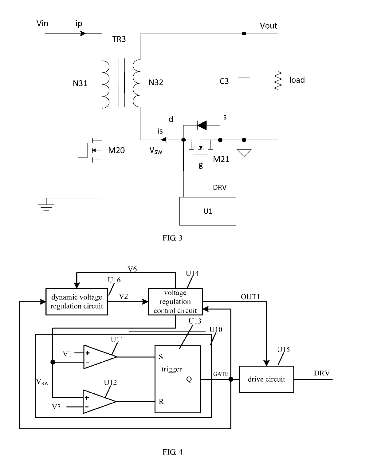
[0039]A synchronous rectification control circuit in the embodiment of the present invention is used for controlling a switching circuit having a synchronous rectification transistor. FIG. 3 illustrates a switching circuit of an embodiment including: a transformer TR3, one end of a primary side winding N31 of a tran...


PUM


Abstract

The present invention provides a synchronous rectification control circuit, a method and a flyback switching circuit. A drive circuit outputs a drive signal to control the turn-on and turn-off of a synchronous rectification transistor; a threshold comparison circuit controls the drive circuit to output a pull-up drive signal to turn on the synchronous rectification transistor when a drain-source voltage is lower than a preset low threshold voltage and controls the drive circuit to output a pull-down drive signal to turn off the synchronous rectification transistor when the drain-source voltage is higher than or equal to a preset high threshold voltage; a voltage regulation control circuit controls the drive circuit to output a drive signal for pulling up a voltage of the drive signal to a preset pull-up voltage high value when the drain-source voltage is lower than a preset voltage regulation reference value.

Description

CROSS-REFERENCE TO RELATED APPLICATIONS[0001]This Non-provisional application claims priority under 35 U.S.C. § 119(a) on Patent Application No(s). 201610855157.1 filed in People's Republic of China on Sep. 28, 2016, the entire contents of which are hereby incorporated by reference.BACKGROUND OF THE INVENTIONField of the Invention[0002]The present invention relates to switching-mode power supply technology and, more particularly, to a synchronous rectification control circuit, a method, and a flyback switching circuit.Description of the Related Art[0003]FIG. 1 is a flyback circuit, which is a common isolated type switching circuit. A primary side N01 of a transformer TR1 is connected with a primary circuit, and an input voltage Vin1 is inputted into a primary circuit. An output current Vout1 flows through a diode D01 at a secondary side N02, the output current Vout1 is loaded to a load, and the load is connected in parallel with a capacitor C01. As the function of electrical equipme...

Claims


Application Information

Patent Timeline
Patent Type & Authority Patents(United States)
IPC IPC(8): H03B1/00H03K3/00H02M1/38H02M1/08H02M7/217H03K5/24H02M1/00
CPCH02M7/217H02M1/38H03K5/24H02M1/08H02M2001/0048H02M3/335H02M3/33592H02M1/0048Y02B70/10
Inventor WONG, PITLEONGREN, YUANCHENGZHOU, XUNWEIZHANG, JUNMINGJIN, YIQING
Owner JOULWATT TECH INC LTD
Why Eureka
Try Eureka