Ignition plug and ignition system including the same

a technology of ignition system and ignition plug, which is applied in the direction of sparking plugs, automatic control of ignition, corona discharge, etc., can solve the problems of defective ignition, low input energy per unit, and low area, so as to suppress the anti-inflammation action of the electrode, the growth of flame is not hindered, and the combustibility after the ignition is promoted

Active Publication Date: 2019-12-31
MITSUBISHI ELECTRIC CORP +1
View PDF21 Cites 0 Cited by
  • Summary
  • Abstract
  • Description
  • Claims
  • Application Information

AI Technical Summary

Benefits of technology

[0016]In an ignition plug according to the present, invention, a ground electrode is formed in a thin-rod shape or mesh-like shape. Thus, sufficiently strong radicals can be locally generated by a dielectric barrier discharge, ignition of fuel is enabled, an anti-inflammation effect by the ground electrode is small, and the growth of flame is hardly hindered. Furthermore, by making the thickness dimension of a second dielectric facing a discharge region uniform, the barrier discharge is spread over the surface of the second dielectric and generation of radicals is maintained, so that combustibility after the ignition is promoted. Moreover, in the case where the second dielectric covers the end portion of a high voltage electrode, by making the area of a ground electrode facing the discharge region smaller than the surface area of the second dielectric facing the discharge region, the fuel is liable to flow into the discharge region and an anti-inflammation action by the electrode is suppressed. Consequently, according to the present invention, the direct ignition of the fuel can be stably performed using the dielectric barrier discharge, and an ignition plug capable of realizing excellent, ignitability and combustibility is obtained.
[0017]In an ignition plug according to the present invention, a ground electrode is formed in a thin-rod shape or mesh-like shape. Thus, sufficiently strong radicals can be locally generated by a dielectric barrier discharge, the ignition of fuel is enabled, an anti-inflammation effect by the ground electrode is small, and the growth of a flame is hardly hindered. Furthermore, by making the thickness dimension of a second dielectric facing a discharge region uniform, a barrier discharge is spread over the surface of the second dielectric and generation of radicals is maintained, so that combustibility after ignition is promoted. Moreover, a distance G2 of a gap between the first dielectric covering the peripheral surface of the high voltage electrode and the main fitting is set to be equal to or smaller than 0.3 mm, and thus a discharge occurring between the first dielectric and the main fitting can be suppressed and electric power loss by the discharge caused in the gap is suppressed. Consequently, according to the present invention, the direct ignition of the fuel can be stably performed using the dielectric barrier discharge, and an ignition plug capable of realizing excellent ignitability and combustibility is obtained.
[0018]Furthermore, in an ignition plug according to the present invention, a ground electrode is formed, in a thin-rod shape or mesh-like shape. Thus, sufficiently strong radicals can be locally generated by a dielectric barrier discharge and ignition of fuel is enabled, an anti-inflammation effect by the ground electrode is small, and the growth of a flame is hardly hindered. Furthermore, a third protrusion having a pointed end portion is provided on a second dielectric at a location facing a discharge region, and thus the effect of decreasing a discharge initiation voltage is obtained. Consequently, according to the present invention, the direct ignition of the fuel can be stably performed using the dielectric barrier discharge, and an ignition plug capable of realizing excellent ignitability and combustibility is obtained.
[0019]Furthermore, in an ignition system according to the present invention, because an end portion of a high voltage electrode of an ignition plug and a ground electrode are disposed to face each other within a combustion chamber, a fuel gas introduced into a combustion chamber is liable to flow into an discharge region, and simultaneously with the occurrence of a dielectric barrier discharge, radicals can react with fuel so as to ignite the fuel. Consequently, according to the present invention, the direct ignition of the fuel can be stably performed using a barrier discharge, and an ignition system capable of realizing excellent ignitability and combustibility can be obtained.
[0020]An object, a feature, a standpoint and an effect other than those described above are probably apparent from the following detailed description of the present invention, which is provided with reference to the drawings.

Problems solved by technology

However, either one has a problem of defective ignition.
On the other hand, because energy input by plasma, spreads throughout into the entire discharge space, input energy per unit, area is low.

Method used


Image

  • Ignition plug and ignition system including the same
  • Ignition plug and ignition system including the same
  • Ignition plug and ignition system including the same

Examples


embodiment 1

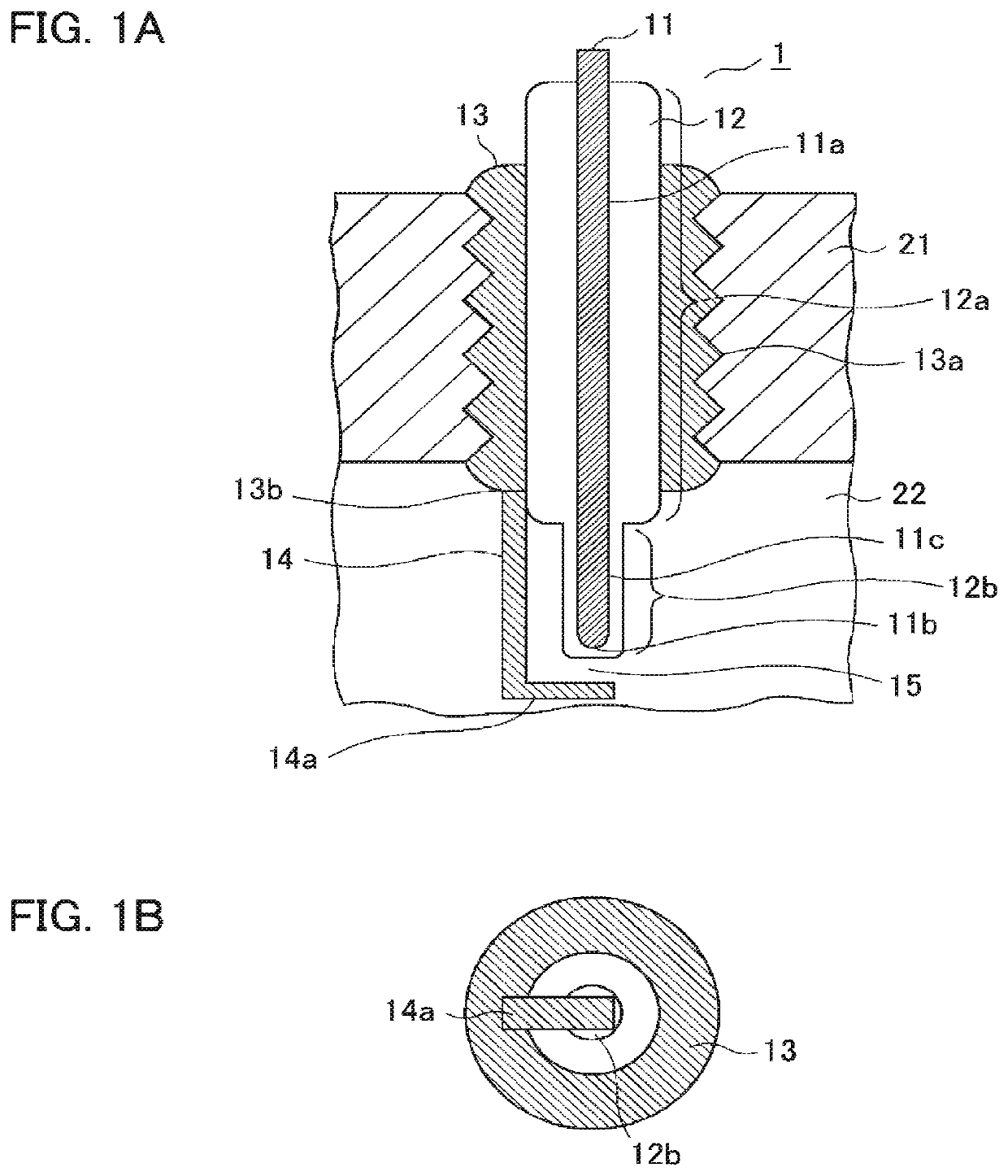
[0054]Hereinafter, an ignition plug according to embodiment 1 of the present invention and an ignition system including the same will be described with reference to the drawings. FIGS. 1A and 1B illustrate a cross-sectional view and a bottom view of the ignition plug according to embodiment 1. As illustrated in FIGS. 1A and 1B, an ignition plug 1 according to embodiment 1 includes a rod-shaped high voltage electrode 11, a first dielectric 12a that covers the peripheral surface 11a of the high voltage electrode 11, a cylindrical main fitting 13, and a rod-shaped ground electrode 14.

[0055]The main fitting 13 that is a case of the ignition plug 1 has a threaded portion 13a in the peripheral surface thereof, and is fixed inside a partition wall 21 that faces a combustion chamber 22 of an engine. The rod-shaped, ground electrode 14 is connected to one end surface 13b of the main fitting 13. The main fitting 13 and the ground electrode 14 have a ground electric potential which is the same...

embodiment 2

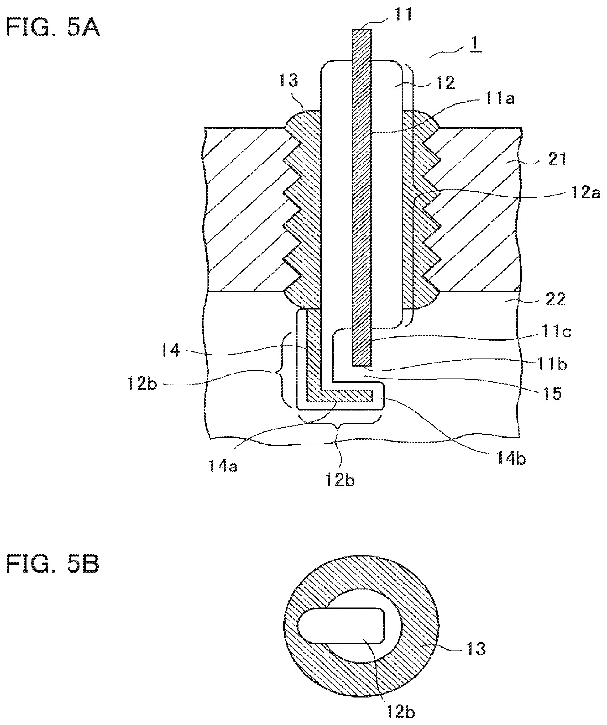
[0066]In embodiment 2 of the present invention, a basic modification of the ignition plug 1 (FIGS. 1A and 1B) according embodiment 1 described above will be described with reference to FIGS. 5A and 5B to FIGS. 7A and 7B. The same or corresponding portions in respective drawings will be denoted by the same reference numerals, and descriptions thereof will be omitted.

[0067]In order to generate the barrier discharge, the second dielectric 12b needs to be interposed between the high voltage electrode 11 and the ground electrode 14. The second dielectric 12b may be provided on any electrodes. In embodiment 1 described above, the high voltage electrode 11 is configured to be covered with the second dielectric 12b, but as illustrated in FIGS. 5A and 5B, the ground electrode 14 may be covered with the second dielectric 12b, thereby being configured as a dielectric electrode. In that case, the end portion 11c of the high voltage electrode 11 is exposed from the dielectric 12.

[0068]Furthermor...

embodiment 3

[0078]In embodiment 3 of the present invention, as a modification of the ignition plug 1 (FIGS. 1A and 1B) according to embodiment 1 descried above, an example in which a protrusion having a pointed end portion or a small metal piece is provided on a surface of the high voltage electrode 11, the second dielectric 12b, or the ground electrode 14, which faces the discharge region 15, will be described with reference to FIGS. 8A and 8B to FIG. 18. In respective drawings, the same or corresponding portions in the drawings will be denoted by the same reference numerals, and descriptions thereof will be omitted.

[0079]In the example illustrated in FIGS. 8A and 8B, the ground electrode 14 is a single metal electrode, and includes a first protrusion 16 having a pointed end portion protruding into the discharge region 15 at a location on the bent portion 14a of the ground electrode 14, which faces the discharge region 15. Furthermore, in the example illustrated in FIGS. 9A and 9B, the ground ...


PUM


Abstract

In an ignition plug, since a ground electrode is formed in a thin-rod-shape or a mesh-like shape, sufficiently strong radicals are locally generated by a barrier discharge, an anti-inflammation effect by the electrode is small, and the growth of a flame is hardly hindered. Furthermore, by making the thickness dimension of a second dielectric facing a discharge region uniform, the barrier discharge is spread over the surface of the second dielectric, the generation of the radicals is maintained, and combustibility after ignition is promoted. Furthermore, because an end portion of a high voltage electrode and a ground electrode are disposed to face each other within a combustion chamber, a fuel gas introduced into the combustion chamber is liable to flow into the discharge region, and is easily ignited by the radicals generated due to the discharge.

Description

TECHNICAL FIELD[0001]The present invention relates to an ignition plug that uses a dielectric barrier discharge and an ignition system that includes the ignition plug.BACKGROUND ART[0002]Regarding a gasoline engine, demand for reduction in fuel consumption is extremely great in terms of the reduction of CO2 or a great increase in gasoline price, and an attempt for improvement of fuel efficiency has been made using a technology such as lean combustion or exhaust gas recirculation. However, either one has a problem of defective ignition. In a spark plug used for a current gasoline engine, a high voltage pulse is applied between electrodes such that thermal plasma is generated by an arc discharge, and the fuel is ignited by the thermal plasma.[0003]In contrast, practical use of a volumetrically high-efficient ignition method using low-temperature plasma has been proposed as a technology for improving the ignition stability. The low-temperature plasma refers to plasma in a non-equilibri...

Claims


Application Information

Patent Timeline
Patent Type & Authority Patents(United States)
IPC IPC(8): H01T13/32F02P5/145F02P13/00F02B23/08F02P3/01
CPCF02B23/08H01T13/32F02P3/01F02P13/00F02P5/145H01T13/50H01T13/34H01T13/467H01T13/52H01T13/54H01T19/04H05H1/2406F02P15/10H05H1/2418F02P23/04
Inventor TAMIDA, TAICHIROINOUE, TAKAHIROHASHIMOTO, TAKASHINAKAGAWA, AKIRASAKASHITA, TOMOKAZUNAGAI, TAKAYOSHITANAYA, KIMIHIKOKAMEDA, HIROYUKIYAMADA, YUICHIBAN, KENJI
Owner MITSUBISHI ELECTRIC CORP
Why Eureka
Try Eureka