Method for improving threshold accuracy in an RFID-device through offset cancellation

Active Publication Date: 2019-12-31
EM MICROELECTRONIC-MARIN
View PDF1 Cites 1 Cited by
  • Summary
  • Abstract
  • Description
  • Claims
  • Application Information

AI Technical Summary

Benefits of technology

The present invention provides a method and a circuit for a detector in an RFID-device that improves the accuracy of the detector circuit. The method takes into account that the input signal is a single-ended signal, but the resulting differential signal has different values in different phases of the clock cycle. The method combines the incoming signal with an offsets common mode signal, which remains constant during the clock cycle. By removing the offsets from the output signal, the detector circuit can produce more accurate results. The method also reduces the parameter variation associated with each circuit, leading to more accurate detector circuits with smaller deviation from the target value. Additionally, the method can be implemented using standard semi-conductor components for a cost-efficient production process.

Problems solved by technology

A significant challenge when designing RFID-readers is the correct detection of the response signal generated by the tags.
In particular, this mismatch, randomly affecting the parameters of equally designed and closely positioned circuit components, is difficult to mitigate and may significantly degrade the performance of the RFID-device as a whole and in particular the achieving of a stable threshold.
However and in addition to increasing the area of the die, this usually reduces the bandwidth of the circuits and implies a higher circuit current in order to meet the performance specifications.
A higher circuit current typically results in an increased power consumption in an RFID-device.

Method used


Image

  • Method for improving threshold accuracy in an RFID-device through offset cancellation

Examples


Embodiment Construction

[0029]Various embodiments are described hereinafter with reference to the Figures. It should be noted that elements of similar structures or functions are represented by like reference numerals throughout the Figures. It should also be noted that the Figures are only intended to facilitate the description of the embodiments. They are not intended as an exhaustive description of the claimed invention or as a limitation on the scope of the claimed invention. In addition, an illustrated embodiment needs not have all the aspects or advantages shown. An aspect or an advantage described in conjunction with a particular embodiment is not necessarily limited to that embodiment and can be practiced in any other embodiments even if not so illustrated, or if not so explicitly described.

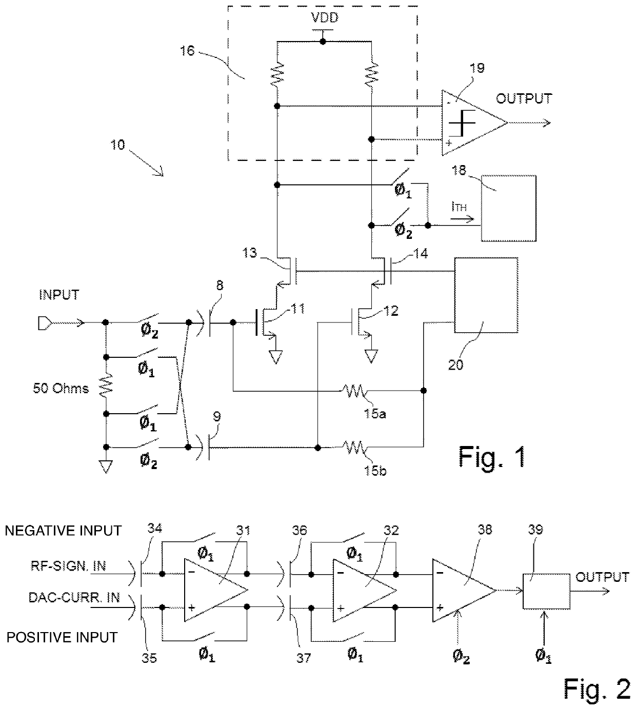
[0030]In FIG. 1 a block diagram of a detector circuit according to one embodiment of the present invention is schematically presented.

[0031]In the following, the components and the operation of the detector circ...


PUM


Abstract

A method for improving threshold accuracy in an RFID-device through offset cancellation, and including the steps of providing a comparator including a first and a second amplifiers, providing a current output digital-to-analogue converter, AC-coupling in an RF-signal into the detector circuit, during a first phase, applying a signal based on the RF-signal into the first amplifier while a current of the DAC is set to zero, and applying a current of the DAC into the second amplifier while a signal based on the RF-signal is set to zero, during a second phase, applying the current of the DAC into the first amplifier while the signal based on the RF-signal is set to zero, and applying the signal based on the RF-signal into the second amplifier while the current of the DAC is set to zero.

Description

FIELD OF THE INVENTION[0001]The present invention primarily relates to the field of detector circuits and in particular to detector circuits suitable for RFID-applications. Moreover, such a detector circuit is normally implemented in a receiver module of an RFID-device, such as an RFID-tag or an RFID-reader.BACKGROUND OF THE INVENTION[0002]Radio Frequency IDentification (RFID) can be used for locating and identifying objects. In this context, the RFID-systems are particularly useful for tracking of a large numbers of objects. These systems usually comprise RFID-readers and RFID-tags. When a power management system of an RFID-tag includes an energy storage device, e.g. a battery, then the tags are known as active tags. RFID-tags powered solely by the received RF-signals are called passive tags.[0003]Intrasystem communication is typically conducted by an RFID-reader interrogating one or more RFID-tags by sending a Radio Frequency (RF) wave. In response, the tag that senses the interro...

Claims


Application Information

Patent Timeline
IPC IPC(8): G06K19/00H03K3/037H03F1/02H03K5/24H03F3/19G06K7/10H03M1/66
CPCH03F1/0205H03K3/037H03K5/24H03F3/19G06K7/10366H03F2200/451H03M1/66H03F3/195H03F3/45475H03F3/45977H03F3/45982H03F3/45986H03F3/45995
Inventor ROTZOLL, ROBERT R.BUESCHER, KEVIN SCOTT
Owner EM MICROELECTRONIC-MARIN
Why Eureka
Try Eureka