
Self-centering phakic refractive lenses with parachute design

a phakic refractive lens and parachute technology, applied in the field of intraocular lenses, can solve the problems of affecting the acceptance of this procedure, affecting the stability of the optics, and affecting the operation, so as to achieve stable centration of the optics, preserve optical function, and reduce the risk of cataract induction of the human crystalline lens

Active Publication Date: 2020-01-07
MEDENNIUM
View PDF22 Cites 0 Cited by
  • Summary
  • Abstract
  • Description
  • Claims
  • Application Information

AI Technical Summary

Benefits of technology

The invention is a posterior chamber floating phakic refractive lens that reduces the risk of complications such as cataract and iris pigment dispersion. The lens design allows for aqueous flow and movement with the eye dynamics, while maintaining optical function. The lens is flexible and soft, and uses a small center hole to achieve stable centration and maintain the gap between the lens and the natural crystalline lens. The invention addresses the risks associated with phakic refractive lens implantation and provides a safer and more effective treatment for refractive errors.

Problems solved by technology

A number of possible complications have slowed the acceptance of this procedure.
These complications have been linked to lens designs that are permanently fixed in the eye through attachment to anatomical structures such as the ciliary sulcus and iris.
Decentration can be associated with a rare but potentially serious complication, movement of the lens past the zonules and into the vitreous cavity behind the natural crystalline lens.
In some people, especially those with very high degree of myopia or hyperopia, the zonules may become weakened and / or detached.
Intraocular pressure elevation and cataract formation are complications from such a lens design.
Even in a fixed lens that has a length matched to the diameter of the eye, which is difficult to achieve, the lens will eventually contact the natural lens, resulting in a subcapsular cataract.
The hole was also found to reduce the optical performance of the lens.
The natural pressure equalizing mechanism has been compromised, effectively creating conditions that could lead to glaucoma.
This did not have a significant effect on the performance of the phakic refractive lens, but continued contact of the phakic refractive lens with the zonules could eventually lead to the complication of zonular dehiscence and dislocation of the lens toward the vitreous chamber (the back of the eye near the retina).

Method used


Image

  • Self-centering phakic refractive lenses with parachute design
  • Self-centering phakic refractive lenses with parachute design
  • Self-centering phakic refractive lenses with parachute design

Examples


example 1

Silicone Phakic Refractive Lens (Prior Art)

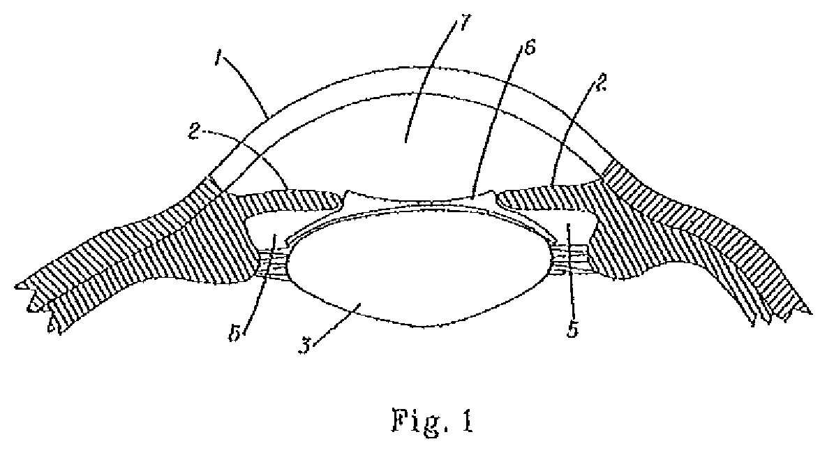
[0026]A small amount of a two-part silicone material with a specific gravity between 0.95 and 1.05 is mixed at a 10:1 ratio and placed in a metal mold. The mold is clamped shut and placed in a curing oven at 120° C. for 70 minutes. The mold is cooled to room temperature, opened, and the phakic lens is carefully removed. The phakic lens has the configuration and dimensions of the lens in FIG. 1.

[0027]The lens is placed in a container with water and the lens can be seen to float on the top of the water. If forced under the water surface, the lens remains floating under the surface. If a stream of moving water is caused to flow under the floating lens, the lens returns to the surface. The lens movement is uncontrolled, with occasional movements towards the side of the container or exaggerated rocking movements.

example 2

Silicone Phakic Refractive Lens with Center Hole

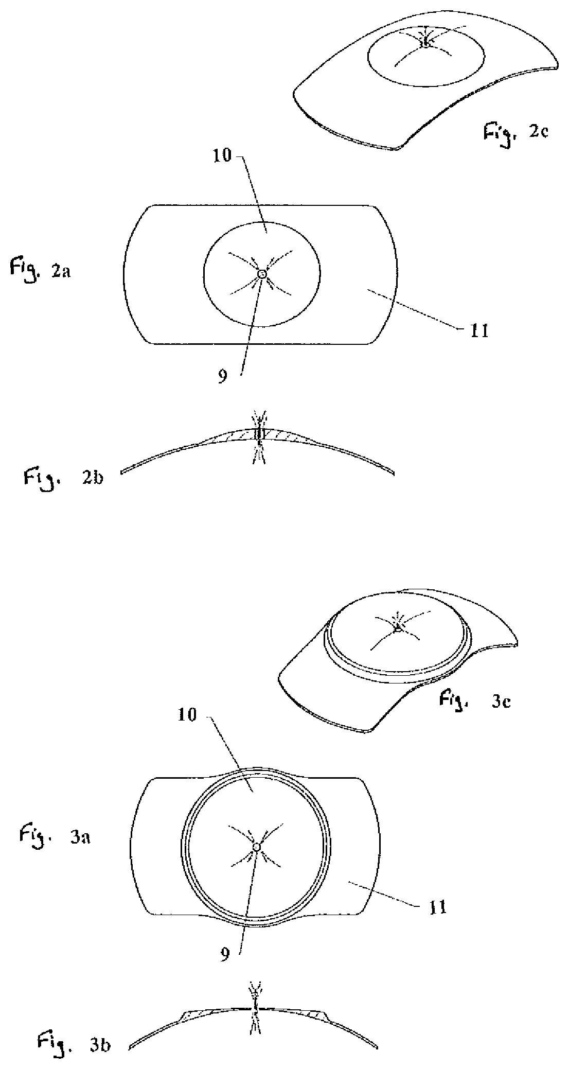
[0028]A small amount of a two-part silicone material with a specific gravity of 0.95 to 1.05 is mixed at a 10:1 ratio and placed in a metal mold. The mold is clamped shut and placed in a curing oven at 120° C. for 70 minutes. The mold is cooled to room temperature, opened, and the phakic lens is carefully removed. A hole with a diameter of approximately 0.4 mm is made in the center of the optic. The phakic lens has the configuration and dimensions of the lens in FIG. 6.

[0029]The lens is placed in a container with water and the lens can be seen to float on the top of the water. If forced under the water surface, the lens remains floating under the surface. If a stream of moving water is caused to flow under the floating lens, the lens returns to the surface. The lens movement is more controlled than the lens with no hole in the center; the lens rises vertically and the lens orientation is conserved.

example 3

Silicone Phakic Refractive Lens with Center Hole

[0030]The phakic refractive lens of Example 2 is evaluated for optical performance and compared to the optical performance of the lens of Example 1 that has no hole in the center of the optic. A commonly used method for evaluating optical performance is to place the lens on an optical bench with a collimator, objective lens, and a US Air Force 1951 Target or similar target image. The ability of the test lens to completely and clearly resolve an image pattern such as a group of closely spaced lines or bars is evaluated as a measure of resolution efficiency and imaging quality. Another measure of imaging quality and optical performance is the modulation transfer function (MTF). It is found that when the center hole is between 0.2 and 0.5 mm in diameter, there is no significant difference in optical performance between the lenses of Example 1 and Example 2.


PUM


Abstract

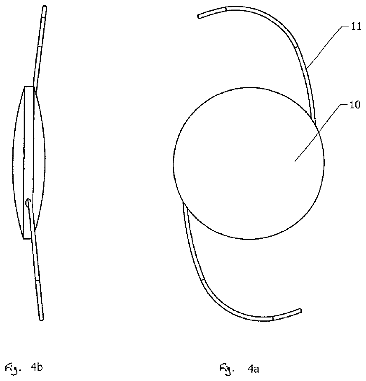
An improved self-centering phakic refractive lens is disclosed. The lens floats freely in the posterior chamber of the eye and corrects vision of the patient but also prevents buildup of intraocular pressure, cataract induction and iris pigment dispersion. The lens comprises an optical body, haptic members which extend outward from the optical body, and a small hole in the approximate center of the optical body for the purpose of allowing aqueous humor to flow through that hole. The lens is designed such that its posterior surface conforms to the shape of the anterior surface of the patient's natural crystalline lens.

Description

TECHNICAL BACKGROUND[0001]This application is a continuation-in-part of U.S. patent application Ser. No. 14 / 661,262, filed Mar. 18, 2015, incorporated by reference herein.[0002]The present invention relates to intraocular lenses implanted into the eye for the correction of vision. When a lens is implanted in an eye that contains a natural crystalline lens, the implanted lens is a phakic lens. A phakic lens may be implanted into the anterior chamber, the area behind the cornea and in front of the iris, or into the posterior chamber that is behind the iris. A posterior chamber phakic refractive lens (PRL) is surgically implanted behind the iris and in front of the human natural crystalline lens for correcting ametropia or refractive errors, such as myopia and hyperopia. Implantation of a phakic refractive lens is the only reversible surgical procedure for correcting severe refractive errors in myopic and hyperopic patients. A number of possible complications have slowed the acceptance...

Claims


Application Information

Patent Timeline
Patent Type & Authority Patents(United States)
IPC IPC(8): A61F2/16A61F9/008
CPCA61F2/161A61F2/1601A61F2002/1689A61F2009/00863A61F2002/1683A61F9/008A61L27/14A61L2430/16
Inventor WILCOX, CHRISTOPHER D.DEMENTIEV, DIMITRIIFELDMAN, JACOBABADIA, JULIAN
Owner MEDENNIUM
Learn More