
DC power generating system with voltage ripple compensation

a technology of voltage ripple and power generation system, applied in the direction of synchronous generator control, generator control by field variation, electric generator control, etc., can solve the problems of high system cost, large voltage ripple at 6-times of pmg fundamental frequency, and objectionable voltage ripple, so as to reduce the voltage ripple

Active Publication Date: 2020-01-21
HAMILTON SUNDSTRAND CORP
View PDF18 Cites 6 Cited by
  • Summary
  • Abstract
  • Description
  • Claims
  • Application Information

AI Technical Summary

Benefits of technology

This patent is about a system and method that can adjust the voltage of a DC power source to reduce voltage fluctuations. The system includes a permanent magnet generator, a passive rectifier, a boost converter, and a controller. The controller controls the boost converter to supply a smooth voltage to a DC bus. This technology can improve the stability and overall quality of the DC power generated.

Problems solved by technology

However, the size of the conventional 2-level six switching device active rectifier often requires large size passive components, such as electromagnetic interference (EMI) filters, DC link capacitor(s) and output power quality filter(s).
However, this approach may require the use of custom SiC power modules resulting in a higher system cost.
This approach, however, typically exhibits a large voltage ripple at 6-times of PMG fundamental frequency.
In many applications such voltage ripple may be considered objectionable.

Method used


Image

  • DC power generating system with voltage ripple compensation
  • DC power generating system with voltage ripple compensation
  • DC power generating system with voltage ripple compensation

Examples


Embodiment Construction

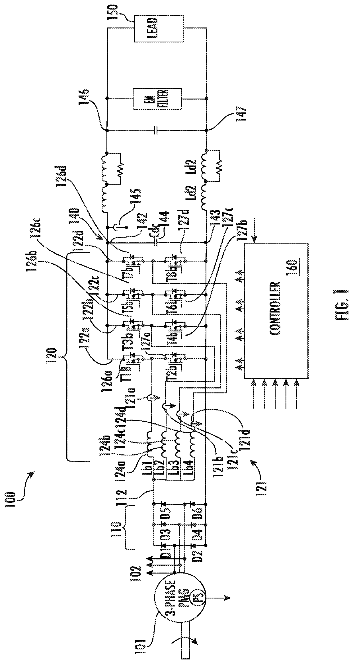
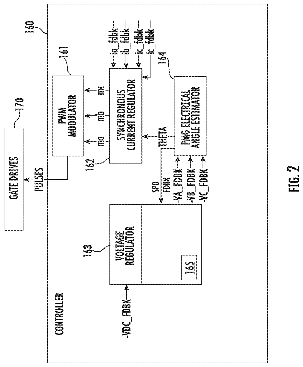
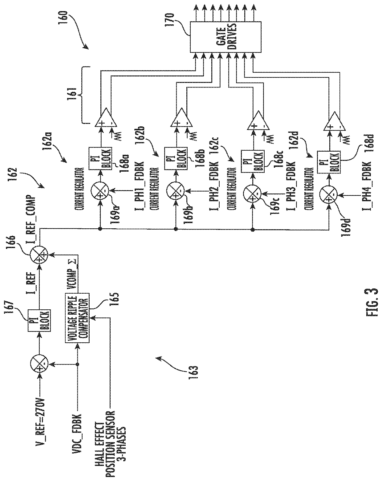
[0034]Embodiments described herein are directed to a system and method DC power generating system for a high voltage DC bus, with example embodiments being discussed below in detail. According to example embodiments, technical benefits and improvements in voltage ripple compensation through active control and compensation. In addition, the voltage ripple compensation of the described embodiments reduces requirements with regard to the size of a DC link capacitor and filtering within the DC power generating system, resulting in improved weight, size and cost for the system.

[0035]A detailed description of one or more embodiments of the disclosed apparatus and method are presented herein by way of exemplification and not limitation with reference to the Figures. As shown and described herein, various features of the disclosure will be presented. Various embodiments may have the same or similar features and thus the same or similar features may be labeled with the same reference numeral...


PUM


Abstract

A method and system for providing voltage ripple compensation in a DC power generation system. The system includes a permanent magnet generator (PMG) and a passive rectifier in operable communication with the PMG. The system also includes a boost converter in operable communication with the passive rectifier and a controller in electrical communication with the boost converter. The controller is configured to cause the boost converter to supply a DC bus and to control the boost converter based on a voltage compensation signal to the boost converter to reduce voltage ripple on the voltage of the DC bus.

Description

BACKGROUND[0001]Exemplary embodiments generally pertain to the field of electric power generating systems (EPGS), and more particularly to high voltage direct current (DC) power generation with active voltage ripple compensation.[0002]Generally, a conventional DC power generating system utilizes a variable-speed permanent magnet synchronous generator (PMG) and an active rectifier. PMG typically offers high efficiency and high power density in comparison with a wound-field synchronous generator construction. However, the size of the conventional 2-level six switching device active rectifier often requires large size passive components, such as electromagnetic interference (EMI) filters, DC link capacitor(s) and output power quality filter(s). To achieve a high power density multilevel topologies, such as Vienna Rectifier, have been considered to achieve low harmonic distortion with moderate switching frequency and reduced EMI emissions compared to a standard 2-level active rectifier / ...

Claims


Application Information

Patent Timeline
Patent Type & Authority Patents(United States)
IPC IPC(8): H02M1/14H02M1/15H02M1/42H02P9/10H02P9/30H02M7/219H02M1/12
CPCH02M1/4233H02M1/15H02P9/305H02P9/10H02M7/219H02M1/12H02M7/06H02P9/00H02P2103/20H02M1/0022H02M1/0025H02M1/007H02M3/1586H02M1/0043H02M3/1582H02M5/4585
Inventor ROZMAN, GREGORY I.MOSS, STEVEN J.
Owner HAMILTON SUNDSTRAND CORP
Learn More