Auxiliary supply for a current supply

a current supply and auxiliary supply technology, applied in the direction of dc-dc conversion, power conversion systems, electrical apparatus, etc., can solve the problems of increased labor, inability to supply components located on the secondary side of the transformer, and inability to use expensive circuits to continue to be supplied, so as to achieve simple and cost-saving matter, the effect of reducing the susceptibility to interferen

Active Publication Date: 2020-01-28
SIEMENS AG
View PDF4 Cites 0 Cited by
  • Summary
  • Abstract
  • Description
  • Claims
  • Application Information

AI Technical Summary

Benefits of technology

[0010]In view of the foregoing, it is therefore an object of the invention to provide an auxiliary supply for a current supply that achieves an improvement over the prior art, in particular lower susceptibility to interference, above all high-frequency interference, in a simple and cost-saving matter.
[0014]The second potential separation unit is used to couple a secondary side reference potential to the primary side with as little resistivity as possible. This makes the auxiliary supply in accordance with the invention much less susceptible to interference (in particular interference caused by high-frequency fluctuations between the primary and secondary side). This means that neither filtering via capacitors, which results in inaccuracies, nor a complex and expensive measuring device is required for the evaluation of signals or information transmitted from the secondary side to the primary side. Only one potential separation unit is used for transmission in the auxiliary supply according to the invention. As a result, the circuit in accordance with the invention is also relatively easy and inexpensive to implement.
[0015]It is furthermore advantageous if, for coupling to the reference potential of the frequency generator, an impedance is connected upstream of the second potential separation unit on the primary side. This impedance can also be formed as a short circuit, i.e., as a resistance with 0 ohm. However, a low-ohmic impedance, for example 100 ohm, which is arranged in series with the second potential separation unit on the primary side, can be used as a protective resistance for example against high voltage pulses from the primary side to the secondary side.
[0017]The first and the second potential separation unit are ideally implemented via capacitors. Hence, energy is transmitted capacitively from the primary side to the secondary side. Furthermore, the use of capacitors has the advantage that standard components can be used and the auxiliary supply implemented in a compact form and inexpensively. For reasons of safety, the capacitors, with which the galvanic isolation unit is implemented are formed as “Y1 capacitors”.

Problems solved by technology

However, components located on the secondary side of the transformer can only continue to be supplied by using expensive circuits if an output voltage from the switched-mode power supply is no longer provided, such as in the event of a short circuit, on remote switch-off or in standby mode.
However, in addition to the use of additional components on the primary side, this procedure also results in a certain inaccuracy in the measurement results.
However, this is also associated with additional effort and above all with significantly higher costs for the entire switched-mode power supply.

Method used


Image

  • Auxiliary supply for a current supply

Examples


Embodiment Construction

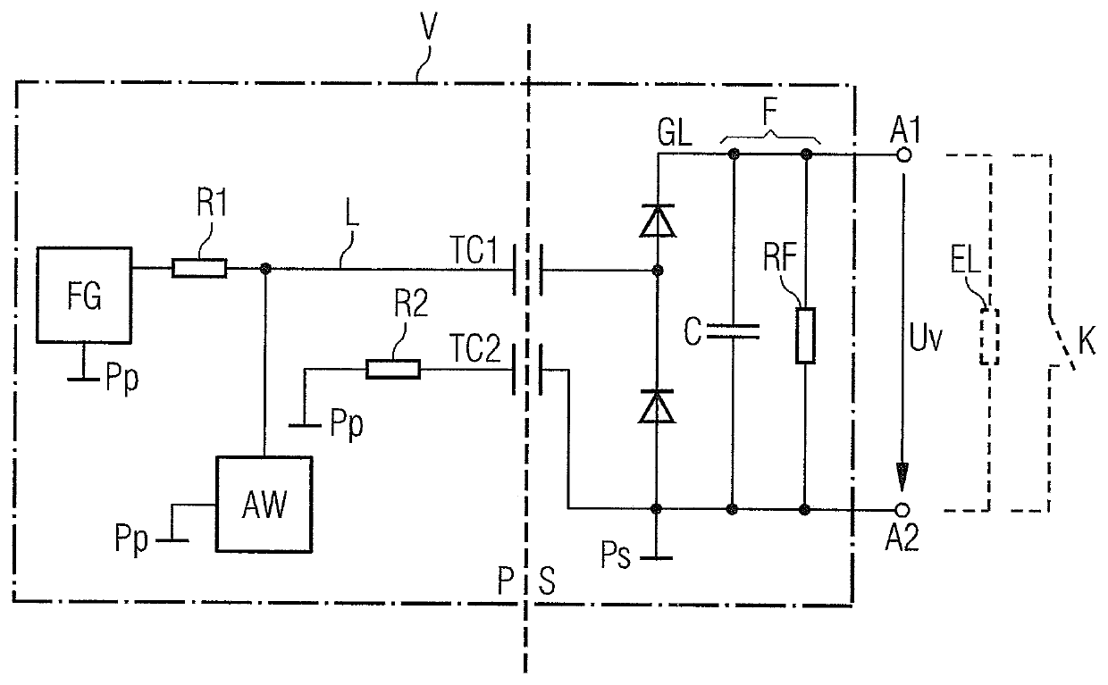
[0022]The FIGURE is an exemplary schematic diagram of an exemplary embodiment of an auxiliary supply V, which can be used in a current supply. For reasons of improved clarity, the actual current supply is not shown in the FIGURE. The current supply comprises at least one transformer or a converter circuit with a transformer. The transformer establishes a galvanic separation unit between a primary side P and a secondary side S. Here, a link to a current source or a current network is usually located on the primary side P of the current supply. An output voltage for connecting a load or a consumer is supplied at the secondary side S of the current supply.

[0023]An auxiliary supply V is provided for a voltage supply for on the secondary side S of the current supply that is independent of the operating state of the current supply. The auxiliary supply V provides a supply current and / or a supply voltage Uv at an output A1, A2 on the secondary side. This supply current or this supply volta...


PUM


Abstract

An auxiliary supply for a current supply with at least one transformer with a primary side and a secondary side, wherein the auxiliary supply includes at least one frequency generator arranged on the primary side for generating an alternating voltage with predetermined frequency, a rectifier unit arranged on the secondary side for a secondary-side supply voltage and first and second potential separation units arranged between the primary side and the secondary side, where the first potential separation unit is connected on the primary side via, for example, a high-value impedance to the frequency generator, where on the primary side, the second potential separation unit has a high-frequency coupling to a reference potential assigned to the frequency generator and provides a low-ohmic capacitive connection between a secondary-side reference potential and the primary side, where it is possible to use a voltage drop at the impedance to evaluate the secondary-side supply voltage.

Description

BACKGROUND OF THE INVENTION1. Field of the Invention[0001]The present invention relates to an auxiliary supply for a current supply comprising at least one transformer with a primary side and a secondary side, where the auxiliary supply provides a voltage supply that is independent of the respective operating state for the secondary side, and where the auxiliary supply includes at least one frequency generator arranged on the primary side, a rectifier unit arranged on the second side for a secondary-side supply voltage and a first and a second potential separation unit arranged between the primary and the secondary sides.2. Description of the Related Art[0002]Current supplies are usually standalone devices or an assembly that are used to supply energy to consumers, i.e., in devices or assemblies. Here, these consumers frequently require a different voltage or a different current than that provided by a current supply network or current / voltage supply source. The current supply conve...

Claims


Application Information

Patent Timeline
Patent Type & Authority Patents(United States)
IPC IPC(8): H02M7/06
CPCH02M7/06H02M5/10H02M3/335H02M1/0003
Inventor RESCHENAUER, STEFAN
Owner SIEMENS AG
Why Eureka
Try Eureka