High efficiency steam engine having improved steam cutoff control

a high-efficiency, steam engine technology, applied in the direction of machines/engines, mechanical equipment, non-mechanical valves, etc., can solve the problems of inability to achieve the thermal efficiency of internal combustion engines, the thermal efficiency of steam powered piston engines cannot match the thermal efficiency of otto or diesel engines developed at the end of the 19sup>th /sup>century, and the inability to operate at speeds over 5000 rpm, etc., to achieve high thermal efficiency

Active Publication Date: 2020-02-04
THERMAL POWER RECOVERY
View PDF29 Cites 3 Cited by
  • Summary
  • Abstract
  • Description
  • Claims
  • Application Information

AI Technical Summary

Benefits of technology

[0006]A more specific purpose of the present invention to retain the high efficiency and other advantages of the Z-Z engine patents noted above while actuating one or more valves by piston movement with little or no valve wear while opening or closing the valve in under 1 millisecond. By achieving these objectives in accordance with the present invention, valve size and weight can be minimized and a lighter weight non-ferrous valve such as a titanium valve can be used to facilitate oscillation at higher speeds. These advantages working together even make it possible in some embodiments to achieve a thermal efficiency exceeding that of a steam turbine in medium to small sizes, such as those under 1000 horsepower while also being lower in cost. The features and advantages noted above also make the invention well suited for applications such as electric power generation or the co-generation of heat and power, to power a vehicle or for use in solar power generation. A major advantage of the invention over internal combustion engines is its ability to use a variety of low grade fuels including waste or unrefined liquid fuels and low cost biomass without producing harmful nitrogen compounds or other air polluting emissions that are generated by internal combustion engines.
[0007]In view of the deficiencies of the prior art it is therefore one object to provide a way of actuating a steam inlet or exhaust valve by piston movement instead of a camshaft while timing at least one steam valve electrically as by means of an electric engine control unit (ECU) without the necessity of forming an inlet valve from a ferromagnetic material.
[0008]It is a more specific object to maintain the high thermal efficiency that characterizes the virtual zero or near zero clearance with zero or near zero pressure steam cycle of U.S. Pat. Nos. 8,448,440, 9,316,130, 9,828,886 and Ser. No. 15 / 794,486 wherein steam admission is controlled electrically through the action of a lightweight steam inlet valve that is able to reciprocate at over 50 cycles per second without the need of a cam shaft or eccentric.
[0009]Another object is to operate valves without the use of a camshaft or eccentric while controlling steam inlet valve cutoff timing electrically throughout a wide range as well as providing continuous variable electrical cutoff regulation under changing speeds and loads when needed to achieve a higher overall thermal efficiency than heretofore found in a reciprocating steam engine.
[0010]These and other more detailed and specific objects and advantages of the present invention will be better understood by reference to the following figures and detailed description which illustrate by way of example but a few of the various forms of the invention within the scope of the appended claims.SUMMARY OF THE INVENTION
[0011]This invention provides a high efficiency steam engine having a steam inlet and exhaust valves that communicate with a steam expansion chamber located in a cylinder between a piston and cylinder head wherein the exhaust valve can be held open by a spring during the exhaust stroke but is closed proximate an end of the exhaust stroke when there is little or no clearance between the piston and cylinder head. The steam inlet valve is held open by a steam pressure differential across it. During operation the steam inlet valve is closed to cut off steam admission to the cylinder under the control of an ECU or other electric current timer that turns on and off electric current supplied to an electromagnet. In a preferred embodiment, an armature is held in contact with the electromagnet by magnetic attraction so that when the current is turned off at a selected time, a pair of springs propel the armature away from the electromagnet to close the steam inlet valve thereby cutting off the flow of steam to the steam expansion chamber. To remove the pressure differential holding the inlet valve open, a reciprocating cutoff control valve is actuated by movement of the armature to remove the pressure differential thereby causing the steam inlet valve to close at the steam cutoff time selected. In one preferred form of the invention a lifter is supported to reciprocate with the piston in a position which closes the cutoff control valve as the piston approaches top dead center thereby sealing off the steam expansion chamber proximate but prior to an end of the exhaust stroke such that only a small residual quantity of the steam remaining in the steam expansion chamber is compressed by movement of the piston at the termination of the exhaust stroke to a pressure sufficient to open the inlet valve due to the force exerted by the steam thus compressed between the piston and the steam inlet valve.

Problems solved by technology

However, the thermal efficiency of steam powered piston engines could not match that of the Otto or Diesel engines developed at the end of the 19th century.
The thermal efficiency of even these engines while improved, could not however reach that of the internal combustion engine.
The valve must therefore be massive and formed from iron which can make operation at speeds over 5000 RPM difficult or impossible.
Another obstacle is the delay caused by the time taken for the magnetic field of an electromagnet to build and then collapse resulting from the induction of a counter EMF which may take as long as 7-10 milliseconds or more.
This limits the speed at which the engine can run especially if more than one valve function must be timed.

Method used


Image

  • High efficiency steam engine having improved steam cutoff control
  • High efficiency steam engine having improved steam cutoff control
  • High efficiency steam engine having improved steam cutoff control

Examples


Embodiment Construction

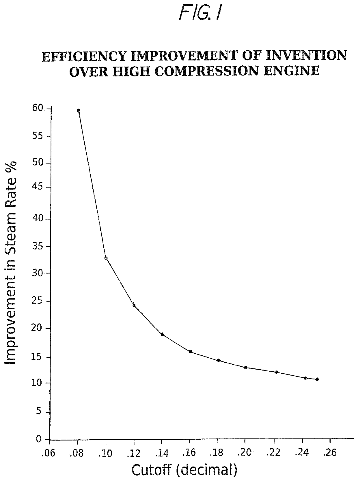
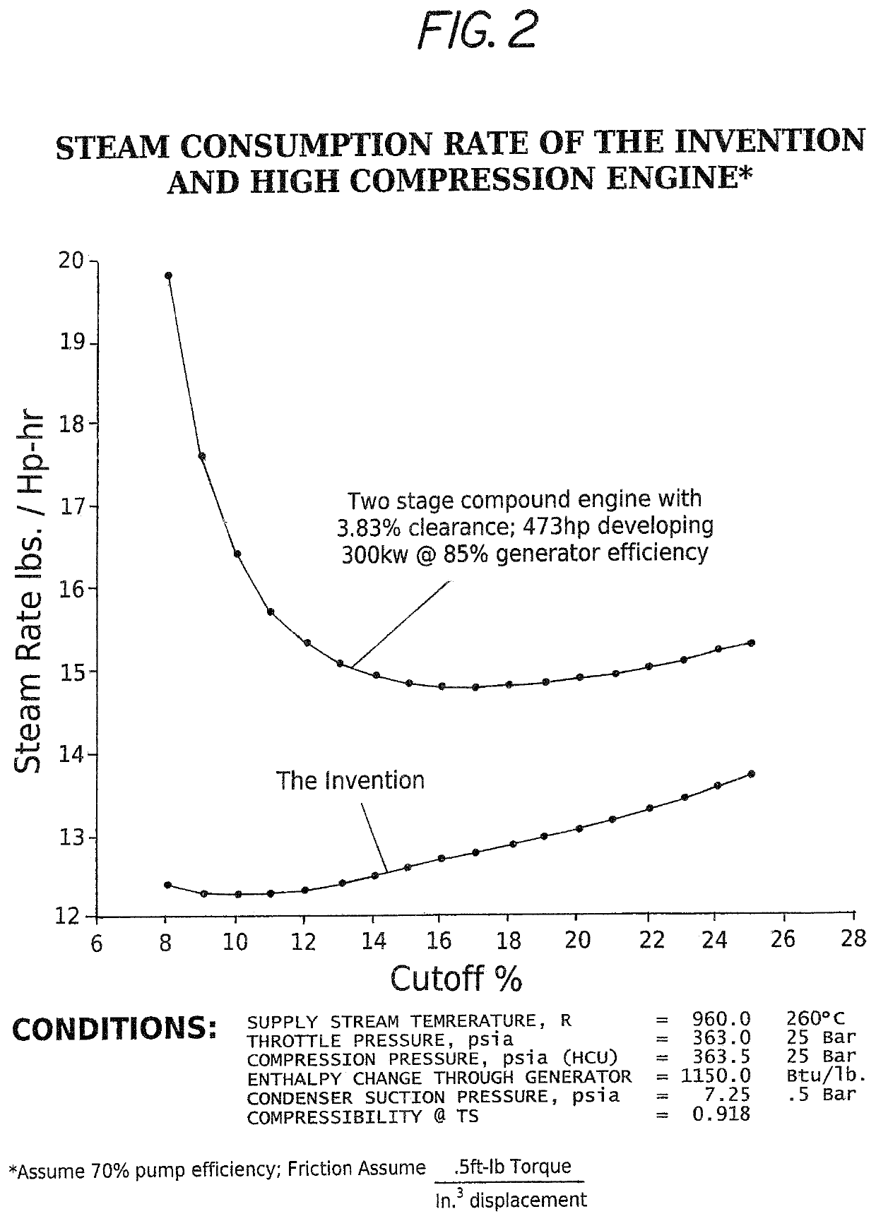
[0019]Refer now to FIGS. 1 and 2 which show how a very sizeable improvement in thermal efficiency is provided by the present invention compared with what is generally acknowledged to be the most efficient uniflow steam engine design known. FIG. 1 which is derived from FIG. 2 shows that at a 16% cutoff the thermal efficiency of the invention is over 15% better, at 12% cutoff it is almost 25% better and at an 8% cutoff where the prior art is at or near a stall condition there is an extraordinary 59% improvement of thermal efficiency in engines using the present invention. The present invention is about 20% better when each engine is run at its optimum efficiency. In a typical steam engine, the efficiency improves as the cutoff is lowered. FIG. 1 shows that it is the lower cutoff range where the present invention produces its greatest improvement.

[0020]FIG. 2 illustrates in the upper graph the performance of a 2 cylinder double expansion high compression steam engine powered by biomass...


PUM


Abstract

A high efficiency uniflow steam engine with automatic inlet and exhaust valves rather than camshaft operated valves includes an electromagnet and cooperating armature that actuates a cutoff control valve for closing a steam inlet valve at any time selected to stop the flow of steam to the cylinder. Approaching the end of the exhaust stroke typically 0.12 inch before TDC the cylinder is sealed thereby compressing the remaining residual steam down to a minute clearance approaching zero, for example, 0.020 inch to raise cylinder steam pressure enough to open the steam inlet valve without physical contact between the piston and the steam inlet valve thereby eliminating tappet noise, shock and wear.

Description

I. CROSS REFERENCE TO RELATED APPLICATIONS[0001]The present application is a continuation-in-part of pending application Ser. No. 15 / 794,486 filed Oct. 26, 2017, which is a continuation-in-part of application Ser. No. 15 / 077,576 filed Mar. 22, 2016, now U.S. Pat. No. 9,828,886, which is a continuation-in-part of application Ser. No. 13 / 532,853 filed Jun. 26, 2012, now U.S. Pat. No. 9,316,130, which is in turn a continuation-in-part of Ser. No. 12 / 959,025, filed Dec. 2, 2010, now U.S. Pat. No. 8,448,440 all of which are incorporated herein by reference.II. FIELD OF THE INVENTION[0002]This invention relates to high efficiency steam engines and to improved valve mechanisms and operating methods for such engines.III. BACKGROUND OF THE INVENTION[0003]Much of the epic progress during the industrial revolution in the United States during the 19th and 20th century was powered by steam. However, the thermal efficiency of steam powered piston engines could not match that of the Otto or Diesel...

Claims


Application Information

Patent Timeline
Patent Type & Authority Patents(United States)
IPC IPC(8): F01L9/04F01B9/02F01B17/04F01B31/26F01L9/20F01L9/40
CPCF01L9/04F01B17/04F01B31/26F01B9/02F01L2009/0478F01B2250/002F01B2250/001F01L23/00F01L9/20F01L9/40
Inventor HARMON, SR., JAMES V.
Owner THERMAL POWER RECOVERY
Why Eureka
Try Eureka