
Plasma generation

a technology of plasma and plasma, applied in the field of plasma generation, can solve the problems of not being able to improve the appearance of the skin, preventing effective treatment of localized irregularities, and changing the skin composition, and achieves a high degree of flexibility and control over the operation, and the effect of fluence in the plasma plum

Active Publication Date: 2020-03-17
FOURTH STATE MEDICINE
View PDF11 Cites 2 Cited by
  • Summary
  • Abstract
  • Description
  • Claims
  • Application Information

AI Technical Summary

Benefits of technology

The present invention provides a high power plasma treatment that can be used for multiple purposes such as cosmetic treatment of wrinkles and skin irregularities. The treatment is performed using a two-stage plasma procedure with a thermal central plasma blade and non-thermal plasma halo, which results in better patient outcomes than prior art low energy non-thermal plasma devices. The treatment can be carried out by trained non-medical personnel and does not require anaesthetic. The plasma torch has an ergonomic grip for easy handling and the plasma touch includes interchangeable ergonomic grips for different uses.

Problems solved by technology

Microdermabrasion is useful for cosmetically treating fine irregularities in the texture of the skin, fine wrinkles and superficial scarring, but it is temporary in its effect and it is typically not capable of improving the appearance of the skin by deep resurfacing and rejuvenation to remove more significant wrinkles and scarring.
However, with dermabrasion there is no fine depth control, and the abrasives have to be applied to a wide area of the skin in order to ‘blend’ the finish, preventing effective treatment of localized irregularities.
Chemical peel procedures use a variety of chemical types which when applied directly to the skin, change the skin composition and cause unwanted skin to slough off the surface.
However, there is no fine depth control available in any chemical peels, and the peel treatment must be applied to the whole area of the skin—e.g. the face, preventing localized treatment.
Chemical peels can often require long recovery periods and also side effects on the skin such as photosensitivity.
Rather than laser treating the entire surface of the skin, laser treatments typically are delivered to a fraction of the skin in a pattern of pinpoints (or Microscopic Treatment Zones, MTZ) spread over an area of the skin, between which healthy skin remains, which reduces healing time and recovery.
As a result of this finish, laser skin resurfacing is not suitable for using in treating small ‘zones’ of skin, as the pattern of pin pricks cannot be blended.
While, unlike for laser light, absorption of the plasma energy is not dependent on the presence of a particular cholorophore (e.g. water present in cells for CO2 lasers) leading to more uniform absorption across cell types, skin types and structures, the low equivalent fluence of the NeoGen™ plasma system means that its ability to reliably and effectively treat deep wrinkles and achieve significant skin resurfacing is questionable.
The lack of any direct skin ablation, combined with the low fluence, means that the usefulness of the NeoGen™ system for skin resurfacing and removal of significant skin irregularities and wrinkles is very limited.
Indeed a large number of repeat procedures may be needed to achieve any noticeable benefit for anything more significant than fine wrinkles and minor skin imperfections.
However, these are invasive interventions that have significant side effects on the appearance of the individual by bulking out skin and paralyzing muscles.
However, the effect of these treatments is not significant and is only short term in benefit, requiring a large number of repeat sessions.

Method used


Image

  • Plasma generation
  • Plasma generation
  • Plasma generation

Examples


Embodiment Construction

[0065]The detailed description set forth below in connection with the appended drawings is intended as a description of presently preferred embodiments of the invention, and is not intended to represent the only forms in which the present invention may be practised. It is to be understood that the same or equivalent functions may be accomplished by different embodiments that are intended to be encompassed within the spirit and scope of the invention. Furthermore, terms “comprises,”“comprising,” or any other variation thereof, are intended to cover a non-exclusive inclusion, such that apparatuses and method steps that comprises a list of elements or steps does not include only those elements but may include other elements or steps not expressly listed or inherent. An element or step proceeded by “comprises . . . a” does not, without more constraints, preclude the existence of additional identical elements or steps that comprises the element or step.

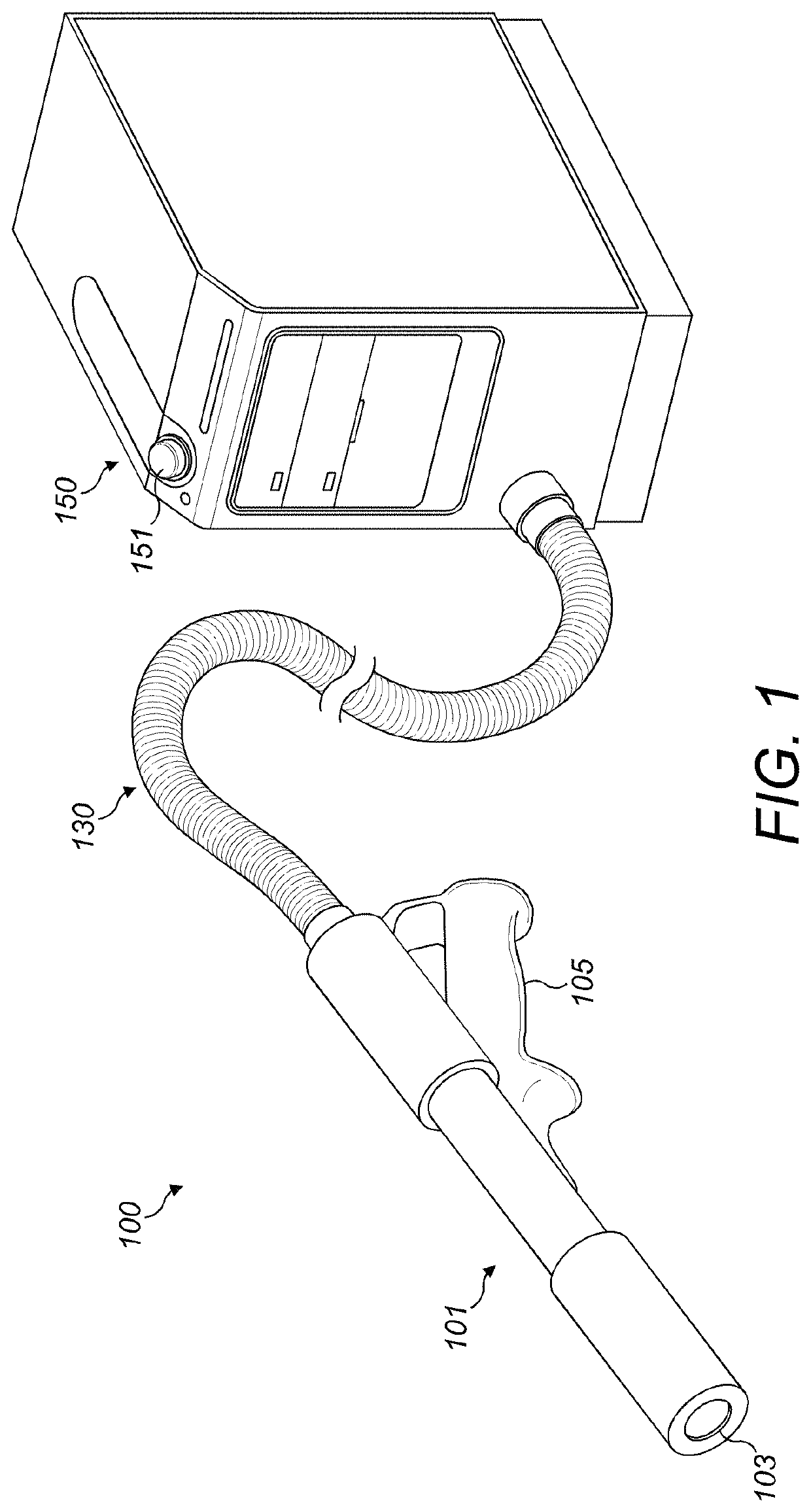
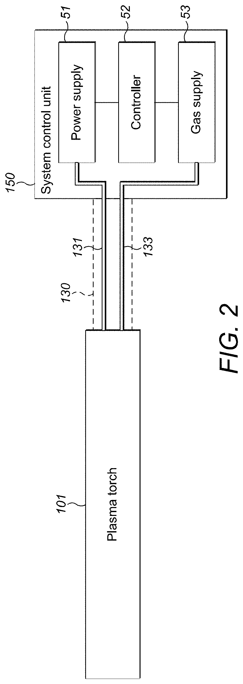
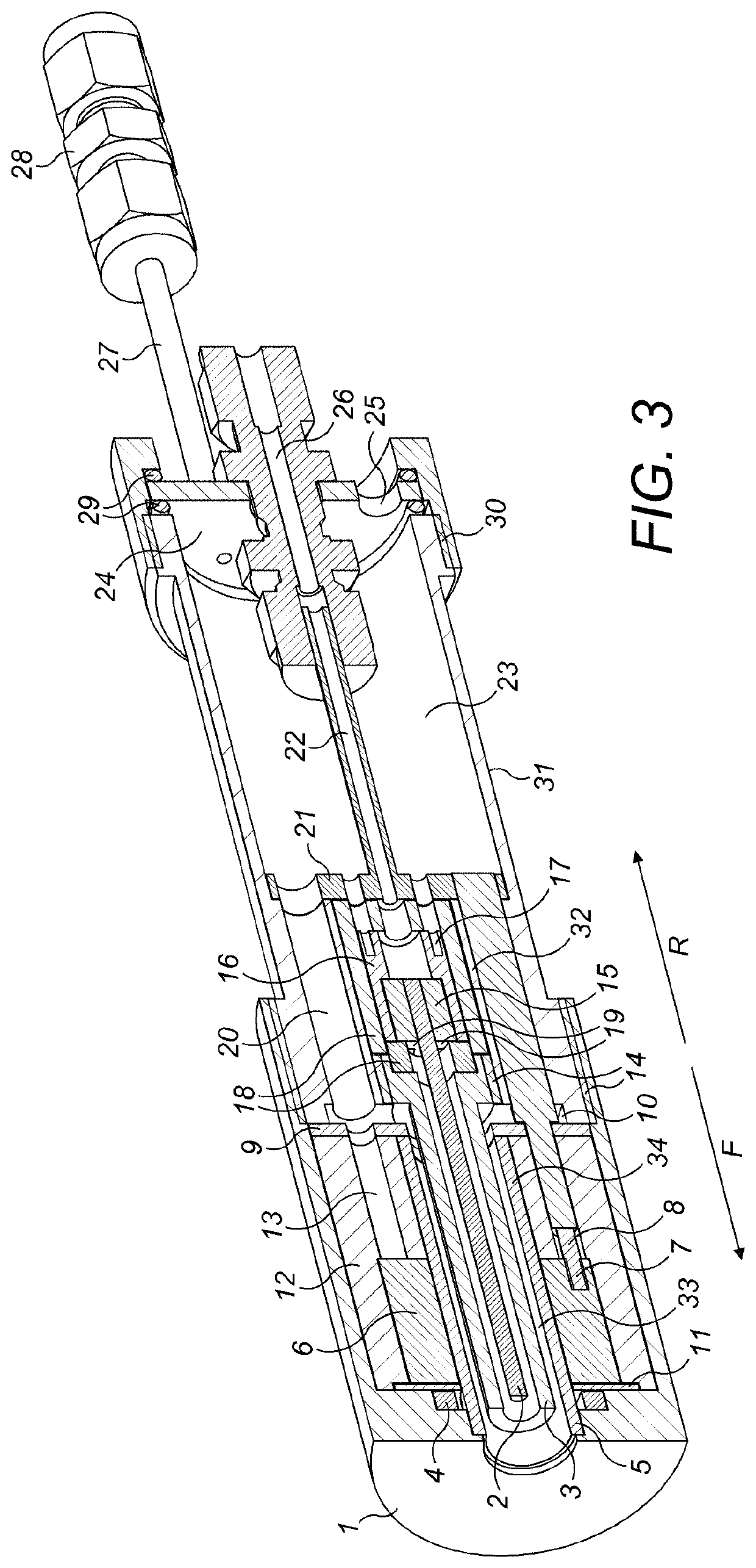
[0066]Referring now to FIGS. 1 and ...


PUM

PropertyMeasurementUnit
energy levelsaaaaaaaaaa
penetration depthaaaaaaaaaa
dielectric constantaaaaaaaaaa

Abstract

A plasma torch having an open end from which a plasma plume is emitted in use is disclosed. The plasma torch includes a central cathode rod, a grounded conductive tube having an open end and being arranged around the cathode and spaced therefrom to form a first cylindrical cavity open at one end; and a high voltage electrode having a dielectric barrier material at a radially inward-facing surface thereof and being arranged around the grounded conductive tube and spaced apart therefrom to form a second annular cylindrical cavity open at one end. A constant direct current (DC) electrical power plus a high voltage pulsed electrical power is provided to the cathode producing an arc discharge in the first cavity between the cathode and grounded tube to generate a central thermal plasma emitted at an open end of the first cylindrical cavity. A high voltage alternating current electrical power or pulsed electrical power is provided to the high voltage electrode producing a dielectric barrier discharge in the second annular cylindrical cavity to generate a non-thermal plasma emitted from an open end of the second cavity as a halo around the central thermal plasma.

Description

RELATED APPLICATIONS[0001]This application is a National Stage Application of International Patent Application WO2016071680, PCT / GB2015 / 053294, filed Nov. 2, 2015, which claims priority to GB Patent Application No. 1419636.4, filed Nov. 4, 2014, all of which is incorporated by reference.FIELD OF THE TECHNOLOGY[0002]The present invention relates generally to plasma generation. In particular, the present invention relates to plasma torches, electrical power generator unit, control modules and methods of operation thereof for producing a cooperative plasma plume having a central thermal plasma blade and a non-thermal plasma halo. The plasma plume finds particular utility in cosmetic treatment of skin, in surgical treatment of wounds and in sterilization of objects in industrial processes.BACKGROUND[0003]Surface ablation of biological tissue is a process used in a variety of medical procedures. An ablation process may be used to remove unwanted tissue and can also be used, in certain ti...

Claims


Application Information

Patent Timeline
Patent Type & Authority Patents(United States)
IPC IPC(8): H05H1/34A61L2/14H05H1/24A61L2/00H05H1/48A61L2/26A61N1/04A61N1/44A61B18/00A61N1/32A61B18/04
CPCH05H1/34A61L2/26A61N1/44A61L2/0011A61L2/14A61N1/0424A61B18/042H05H1/48H05H1/2406A61B2018/00476A61B2018/00577A61L2202/24A61N1/328A61B2018/00452A61L2202/21A61N1/0468A61B2018/00595H05H2001/3484A61L2202/11H05H1/26H05H1/3484
Inventor KNOLL, AARONHARLE, THOMASSHAW, PETERFRAME, THOMASWANTOCK, THOMAS
Owner FOURTH STATE MEDICINE
Learn More