
Copper crystal particles having a highly preferred orientation and a preparation method thereof

a technology of copper crystal particles and highly preferred orientation, applied in the field of electrophoresis, can solve the problems of low production efficiency, inability to easily obtain copper with highly preferred orientation, and low electrodeposition efficiency

Active Publication Date: 2020-03-31
SUZHOU SHINHAO MATERIALS
View PDF9 Cites 0 Cited by
  • Summary
  • Abstract
  • Description
  • Claims
  • Application Information

AI Technical Summary

Benefits of technology

The present invention is a method for coating copper using a direct current electroplating process with a copper sulfate-sulfuric acid system and copper plating additives. This method achieves high-speed plating with a preferred orientation for copper crystal particles in the microstructure of the coating layer that can be controlled. Compared with conventional methods, the present invention reduces complexity, production costs, anizes the coating layer, and improves production efficiency. The addition of copper plating additives increases the capacity for current density in the electroplating process, realizing high speed plating.

Problems solved by technology

Copper with highly preferred orientation, however, cannot be easily obtained, especially in the field of microelectronics.
The current density for pulse electrodeposition is relatively low, usually less than 5 A / dm2, which results in low production efficiency.
In addition, pulse electrodeposition cannot control the degree of preferred orientation to obtain copper crystal particles with preferred orientation.

Method used


Image

  • Copper crystal particles having a highly preferred orientation and a preparation method thereof
  • Copper crystal particles having a highly preferred orientation and a preparation method thereof
  • Copper crystal particles having a highly preferred orientation and a preparation method thereof

Examples


example 1

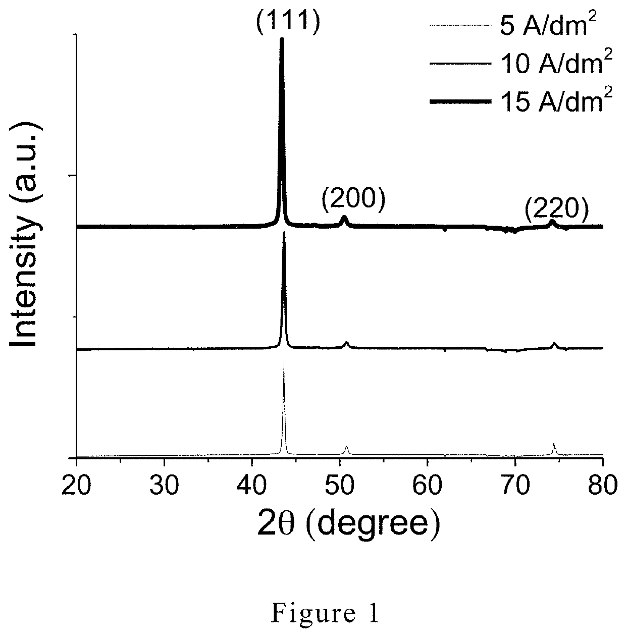
[0057]Copper plating additives were added to a copper plating base solution to obtain a copper plating solution. The copper plating base solution included copper sulfate, sulfuric acid, and a trace amount of hydrochloric acid. In the copper plating solution, the concentrations of an accelerator, a suppressor, and non-dye leveler were 3-5 mL / L, 5-15 mL / L, and 25-35 mL / L, respectively. The concentration of copper ions is 40-60 g / L, the concentration of sulfate ions is 80-120 g / L, and the concentration of chloride ions is 40-60 ppm. The copper plating solution was stirred for 1.5-2.5 hours to mix well.

[0058]The accelerator is sodium lauryl sulfate, disodium 3,3-dithiobispropane-sulphonate, or 3, 3′-dithiobispropanesulfonic acid.

[0059]The non-dye leveler is

[0060]

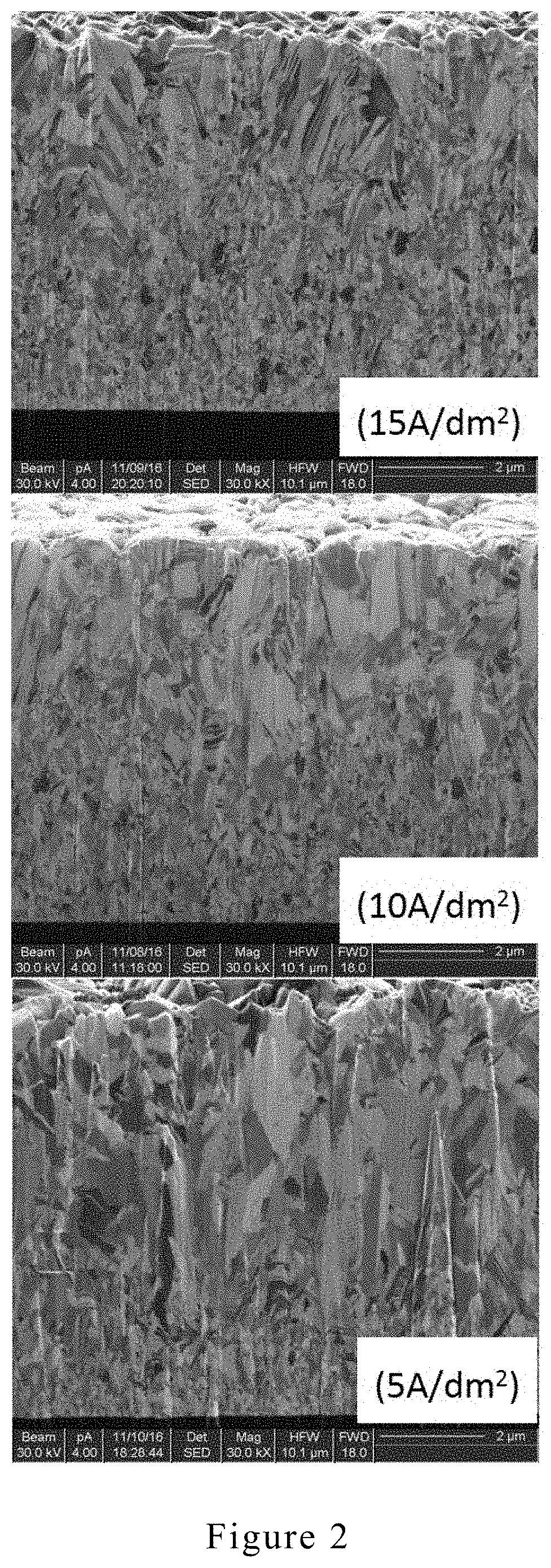
[0061]Substrates were electroplated at three different direct current densities, 5 A / dm2, 10 A / dm2 and 15 A / dm2, for 15 min, 7.5 min, and 5 min, respectively, using the copper plating solution prepared above.

[0062]Plating condit...

example 2

[0072]Copper plating additives were added to a copper plating base solution to obtain a copper plating solution. The copper plating base solution included copper sulfate, sulfuric acid, and a trace amount of sodium chloride. In the copper plating solution, the concentrations of an accelerator, a suppressor, and non-dye leveler were 3-5 mL / L, 5-15 mL / L, and 25-35 mL / L, respectively. The concentration of copper ions is 40-60 g / L, the concentration of sulfate ions is 80-120 g / L, and the concentration of chloride ions is 50 ppm. The copper plating solution was stirred for 1.5-2.5 hours to mix well.

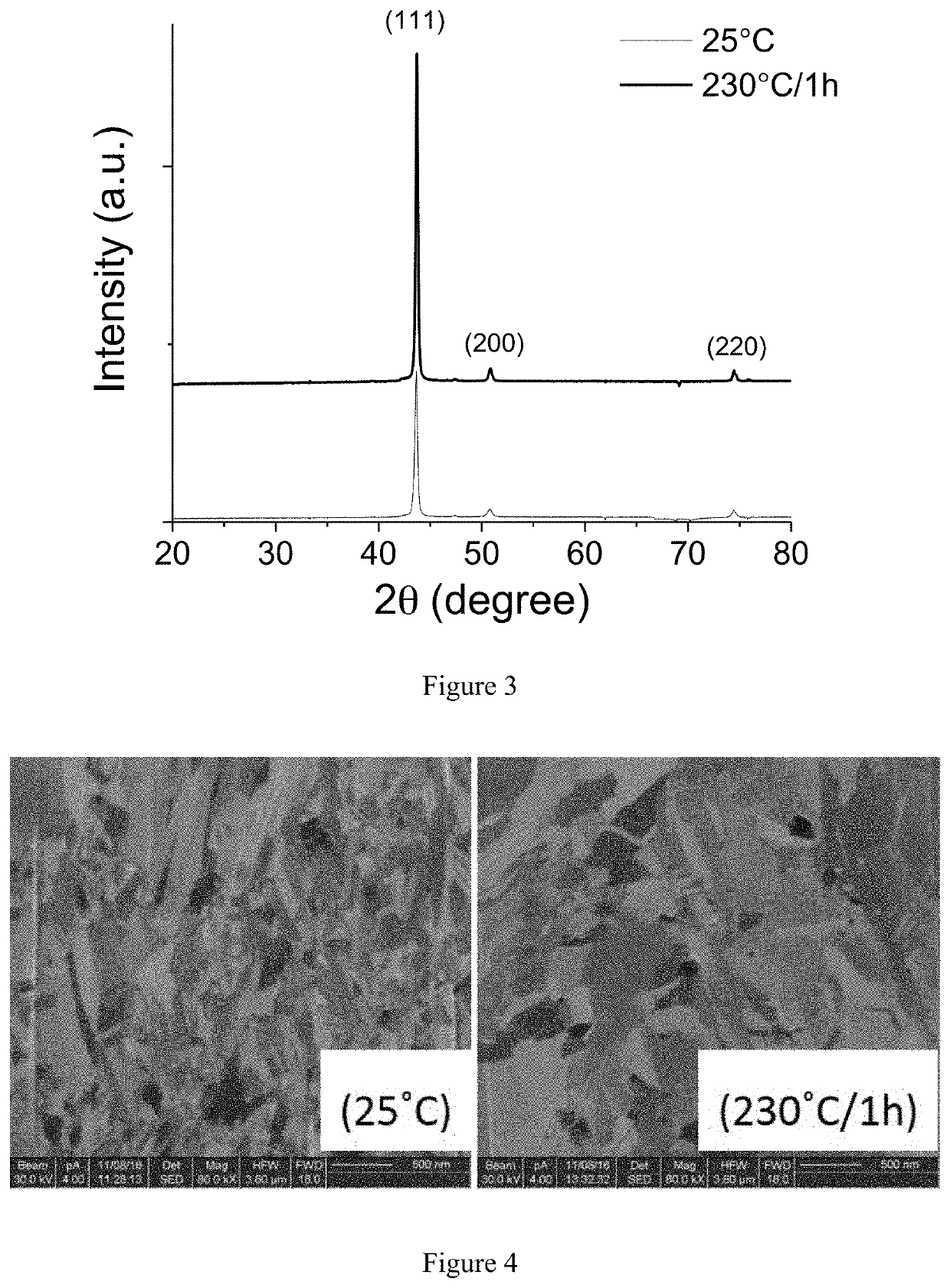
[0073]Two substrates can be electroplated at 5-15 A / dm2 for 5-15 min using the copper plating solution prepared above. One copper coated substrate were then placed in a nitrogen-protected annealing furnace and annealed at 200-300° C. for 0.5-2 h.

[0074]The XRD patterns of the copper coated substrates of the annealed substrate and unannealed substrate were measured by X-ray diffractometry and ar...

example 3

[0077]An inventive electroplating copper was obtained with the same plating conditions described in Examples 1 and 2. A cross-sectional microstructure (SEM, Mag. ×5,000) of the inventive electroplating copper is shown in FIG. 5A. As shown in FIG. 5A, the inventive electroplating copper has bamboo-like structure.

[0078]A cross-sectional microstructure (FIB) of the inventive electroplating copper is shown in FIG. 6A. As shown in FIG. 6A, the inventive electroplating copper is obtained at under high plating speed (i.e., 10 ASD) has bamboo-like structure and uniform particle size.


PUM

PropertyMeasurementUnit
current densityaaaaaaaaaa
concentrationaaaaaaaaaa

Abstract

An electroplating copper layer includes bamboo-like copper crystal particles having a highly preferred orientation. The bamboo-like copper crystal particles have a long axis direction and a short axis direction, and the bamboo-like copper crystal particles have a length of 20 nm to 5 μm in the long axis direction and a length of 20 nm to 2 μm in the short axis direction. A method of preparing the bamboo-like copper crystal particles is also disclosed.

Description

[0001]The present invention is the national stage application of PCT / CN2017 / 103498, filed on Sep. 26, 2017, which claims priority to Chinese Patent Application No. 201611037367.6, filed on Nov. 23, 2016, which is incorporated by reference for all purposes as if fully set forth herein.FIELD OF THE INVENTION[0002]The present invention relates to the field of electroplating, and more particularly to copper crystal particles having a highly preferred orientation and a method of preparing the same by direct current plating.BACKGROUND OF THE INVENTION[0003]Copper with highly preferred orientation has many excellent properties. Because copper crystal particles have highly preferred orientation, their properties are different in different orientations. For a microscopic point of view, different crystal orientations lead different atomic arrangements and densities, resulting in different thermodynamic and electromagnetic properties. In addition, from the chemical reactivity point of view, di...

Claims


Application Information

Patent Timeline
Patent Type & Authority Patents(United States)
IPC IPC(8): C25D15/00C30B29/02C25D3/38B32B15/01C30B28/04
CPCC30B28/04C30B29/02C25D3/38B32B15/01C07D219/02C07D311/84C07D335/10C30B29/60B32B2307/704B32B2311/12
Inventor ZHANG, YUNWANG, JINGZHU, ZIFANGMA, TAOCHEN, LUMING
Owner SUZHOU SHINHAO MATERIALS
Learn More