Articulating moored profiler system

a profiler and mooring technology, applied in the field of articulating moored profiler systems, can solve the problems of limited functionality, limited profile over time, and limited sampling depth, so as to reduce drag, minimize power consumption, and reduce drag

Active Publication Date: 2020-04-07
WOODS HOLE OCEANOGRAPHIC INSTITUTION
View PDF8 Cites 2 Cited by
  • Summary
  • Abstract
  • Description
  • Claims
  • Application Information

AI Technical Summary

Benefits of technology

[0050]A key advantage of the present invention is the ability to manipulate the vessel body 0 both to align the vessel body 0 with the relative three-dimensional incident flow, thereby reducing drag, and to align the sensors 1 such that they are able to sample undisturbed waters. Additionally, the system is designed to align relative to the current flow to harness the flow forces to thereby assist the system in profiling upward to minimize power consumption. Existing profiler models have struggled to perform in the face of the drag forces exerted upon the profiler body and vortex shedding when attempting to operate in strong current environments, causing the profiler to lose traction, fail to profile over the programmed depth interval, and deplete the power source prematurely. The instant AMP solves this problem because the longitudinal vessel body 0 is able to articulate about the mooring wire 10 to align with the relative three-dimensional incident flow. As depicted, the improved Articulating Moored Profiler incorporates an articulating mechanism 8 that allows the hydrodynamic body of the profiler to rotate, pivot, and align both horizontally about a cable and vertically in response to the three-dimensional incident relative current flow past the profiler. Depending on orientation, the longitudinal body may need to either be able to articulate vertically or horizontally (or both) about the mooring wire 10 to align with the relative three-dimensional incident flow, so it is important for the pivot mechanism to be able to accommodate the articulation needed for the set up. In certain embodiments, the articulating mechanism 8 allows the vessel body 0 to articulate 360 degrees horizontally about the mooring cable 10. In various embodiments, it may be desirable for the AMP to be able to pivot ±90 degrees about its attachment point to the truck 5c that supports the drive and spring-mounted guide wheel sheeves. In certain embodiments, the vessel body 0 is able to articulate substantially vertical up to ±90 degrees relative to the mooring cable 10. In other embodiments, the articulating mechanism 8 may be adjusted to only allow the vessel body 0 to pivot to a designated degree relative to the mooring cable 10 such that the body may only up to an angle of 45 degrees, 60 degrees, and so forth in one or both vertical (up / down) and horizontal directions.
[0051]As depicted, the articulating mechanism 8 comprises a lockable and rotatable bracket or gear connected to both the vessel body 0 and to the attachment mechanism 5, generally through or in proximity to the drive motor assembly 2. Numerous types of hinges, brackets, ball joints, and other connected may be employed that are capable of allowing a pivot action between the vessel body 0 and the mooring wire 10. As the AMP adapts, either by active or passive manipulation, to provide the most efficient position to reduce drag in these strong flow environmental conditions or to orient sensors as may be desired, these forces have substantially less effect on movement control and reliability. By orienting into the relative flow, the AMP also improves the quality of data from sensors mounted on its leading end. Any wakes from the mooring wire or vehicle body are downstream from the sensing volume of the probes so the water being sampled is relatively undisturbed.
[0052]Typically located in the aft end of the longitudinal vessel body 0 is a power supply 9 in the form of a battery to power the sensors and the drive means. It should be noted that the AMP is designed to be used in marine environments and therefore pressure will be exerted on the unit and its components. This can be particularly detrimental to batteries and smaller electronics so it can be advantageous to employ pressure case(s) for batteries and to adapt the main controller for deep water (e.g., up to 1,000 m, 3,000 m, 6,000 m, 6,500 m, 8,000 m, and full ocean depth). The device may employ a main power source and additional battery packs for backup power. In some embodiments, the power supply 9 is a rechargeable battery such as a rechargeable lithium battery; however, the power supply may include any suitable power source that can power the device through profiling completion either with or without the use of the lift assist system 6 described in more detail below.
[0053]Energy efficiency is a large problem in underwater profilers as the power generally has to be provided onboard the vessel, particularly when the vessel is to be deployed at great depths. Thus, to increase the profiling endurance of the unit in operation, the AMP further incorporates, in one or more embodiments, numerous energy saving mechanisms. Endurance is defined by the distance of cable traveled by the profiler during a mission. The articulating mechanism 8 in combination with the streamlined vessel body 0 has substantially increased endurance to about 2 million meters, double of previous profiler endurance. Additionally, the lift assist system 6 further adds to the device endurance as well as increases battery usage which may be applied to longer profiling missions, more sample measurements, and / or additional or high power-consuming sensors.
[0054]One of the more promising energy saving mechanisms is through the incorporation of a lift assist system 6. As depicted, the lift assist system 6 comprises at least one of a wing set 6a and a fin set 6b (e.g., adjustable wing set, adjustable fin set). Several embodiments of the inventive system employ both a wing set 6a and a fin set 6b. Additional embodiments may utilize more than one wing set 6a and one or more fin sets 6b. In other embodiments, the device comprises a wing set 6a or a fin set 6b. In additional embodiments, the device comprises a lateral fin set arranged laterally on the vessel body 0 in an orientation adapted to be controlled by the lift control system 7 or in a fixed orientation.
[0055]As shown in FIGS. 4 and 5, the wing set 6a is arranged forward on the vessel body 0 aligned with the attachment mechanism 5. In other embodiments, the wing set 6a is arranged near or at the middle section of the vessel body 0. The wing set 6a may be controlled by the drive motor assembly 2 or lift control system 7 to obtain the optimal angle of attack for propelling force or in other cases may be securely attached in a fixed orientation at a specified angle using fasteners.

Problems solved by technology

Despite advances in drifting, gliding, and self-propelled autonomous instruments, use of these technologies to form “virtual moorings” over long time periods are only practical in modest ocean current environments.
Traditional moored profilers are deployed on a bottom-anchored mooring; therefore, they generally remain on station even in strong flows, but their functionality is limited.
For example, while the traditional profiler may be preferable to single observations, the profile over time is severely constrained by a limited number of sampling depths.
Maintaining calibration of many instrument packages is time-consuming and expensive.
Since each preselected depth requires its own complete instrument package, the cost to obtain the data increases proportionately to the number of sites selected.
While these models have returned unique and valuable observations, such models have also suffered from endurance issues (often less than 1,000 km of profiling per deployment).
This endurance problem is particularly problematic as profilers are routinely meant to be disposed in the water column for time periods of a year or longer.
Additionally, these profilers lack the ability to provide reliable track records for profiling.
Likewise, traditional profilers have suffered great issues with reliability with regards to data collection and retention.
A frustrating number of mooring profiler deployments have returned incomplete profiles and / or sampled for less than planned periods due to issues such as premature battery depletion.
Given the number of variables at play in an ocean environment, a failed or only partially successful deployment means, from a scientific standpoint, the complete loss of information that will likely never be acquired or duplicated.
These performance issues have dampened community interest in using and inventing in profilers.
Existing moored systems also suffer from a number of other functional defects.
For example, they routinely fail to reach bottom stop depth while having limits on depth of operation.
Others slip by losing traction of the drive wheel.
Still others have suffered from lost performance in strong water currents.
As a whole, the units have been unreliable at times, either concerning the ability to stay at specific depth when resting between profiles or inconsistent profiling speeds or unreliable time series and data collection which causes profiles to exceed allotted amounts of batter power.

Method used


Image

  • Articulating moored profiler system
  • Articulating moored profiler system
  • Articulating moored profiler system

Examples


example 1

[0070]The drag of the AMP was estimated and compared to estimates of the drag of the McLane Moored Profiler (“MMP”) from the prior art. The drags were estimated for a state with 30 cm / s current while the profiler is traveling along the mooring cable at 30 cm / s. Much of the drag of the MMP and most of the drag of the AMP is from the bluff cable guides, guide wheels, drive motor, CTD, and acoustic current sensor. When there is zero current, these bluff bodies are in line, and the downstream bodies are in the wakes of the upstream bodies, reducing drag. When the current is 30 cm / s, each bluff body is in fresh flow and does not benefit from wake shading.

[0071]The total MMP drag is estimated to be 8.6 N of which 6.1 N is in the direction of profiler movement. The MMP body drag is estimated to be 3.8 N. The AMP as described herein used a low-drag body in the longitudinal vessel body 0, which is streamlined and pointed into the flow, keeping the boundary layer attached. The bare body is es...

example 2

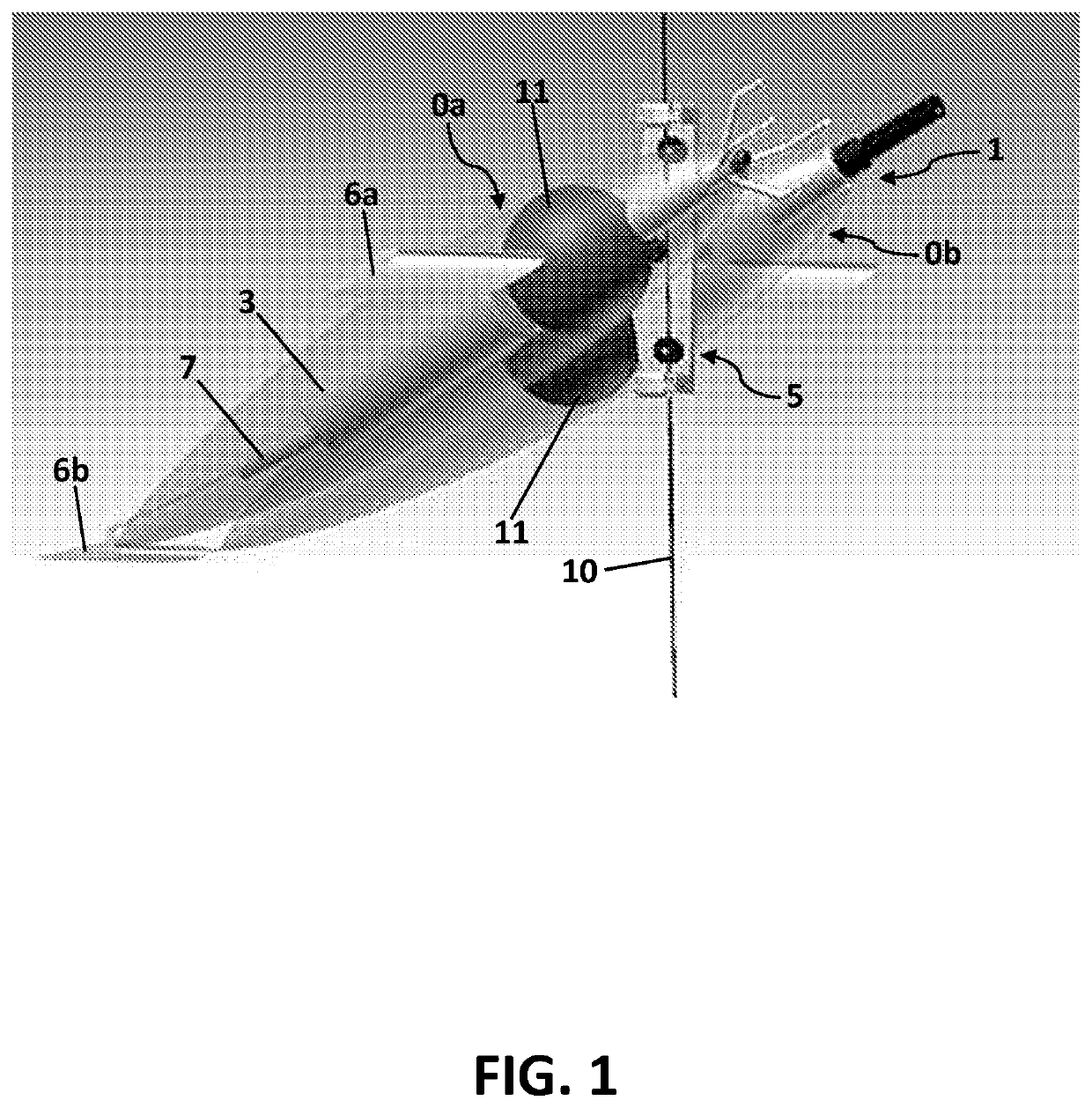
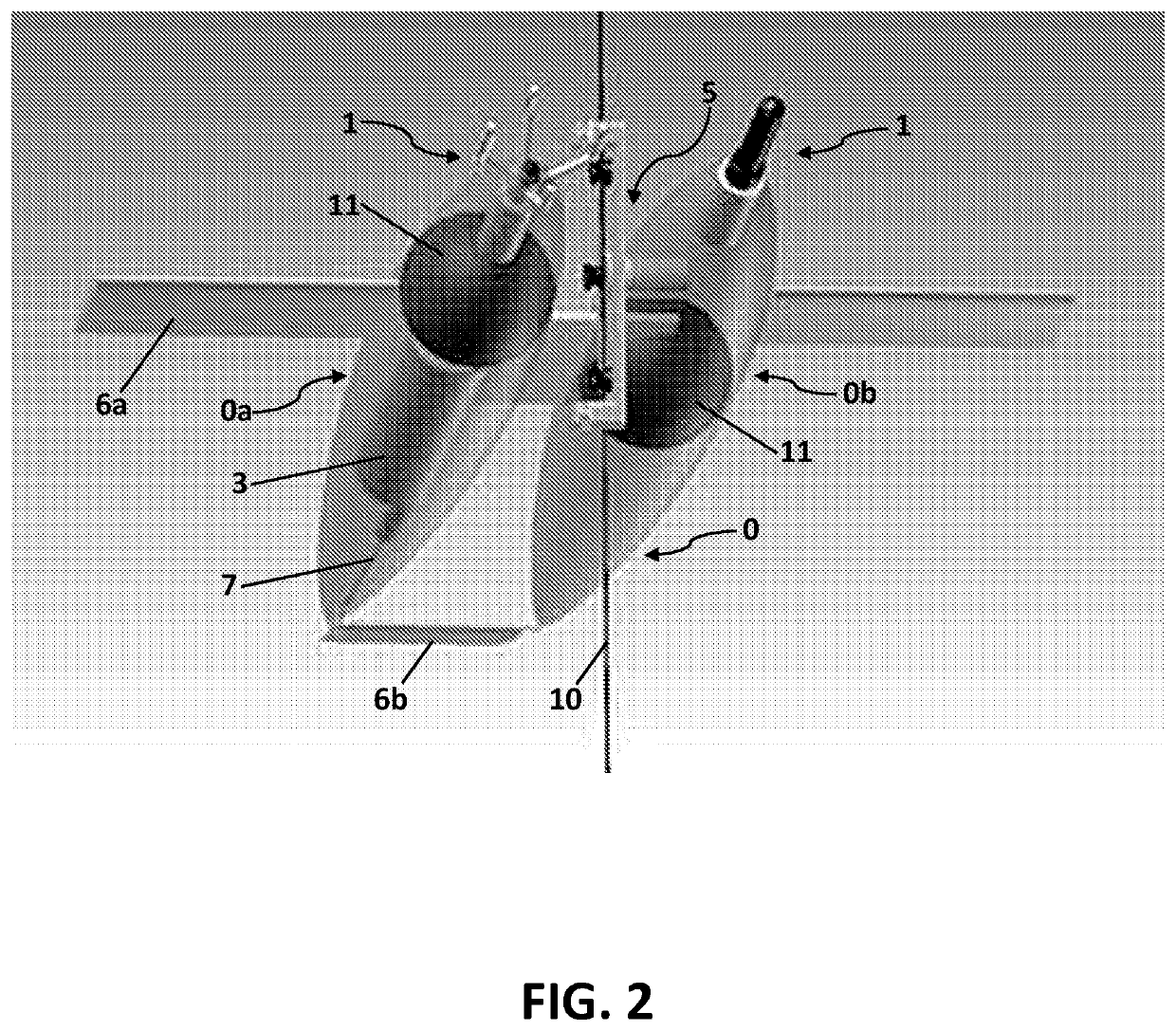
[0076]As depicted in FIGS. 1 and 2, this embodiment of the inventive device employs two vessel bodies 0a and 0b coupled together spatially separated by a connection near the middle sections of the bodies 0a and 0b. This connection is capable of providing electrical signals, power, data communication, etc. between the two vessel bodies 0a and. 0b or may only provide a mechanical engagement between the two bodies. The mooring cable 10 is typically disposed between the two bodies and engaged with the attachment mechanism 5.

[0077]Vessel body 0a is adapted to incorporate the electronics housing 3 and the lift control system 7 within the internal space. As shown, the buoyancy sphere within vessel body 0a is shifted forward relative to buoyancy sphere in vessel body 0b to compensate for the difference in weight distribution. The position of the buoyancy spheres 11 needs to account both for the overall buoyancy / weight and fore-aft balance about the pivoting point of the articulating mechani...

example 3

AMP Specifications

[0078]The following table lists specification for one embodiment of the present invention. While the materials listed are suitable, other materials of similar properties may be used. For example, many structural components are comprised of ultra-high molecular weight (UHMW) polyethylene but may be substituted for a material with similar properties including high abrasion resistance, high melt viscosity, low coefficient of friction, chemical resistance, load-bearing strength, and impact strength.

[0079]

TABLE 1DimensionsLength85.0 inWidth17 inSensor ArraySensorsCTD SensorMAVS SensorDrag (at 30 cm / s current)Total Device Drag3.5 NVessel Body Drag0.2 NProfiling SpeedUp / Down25 cm / s-35 cm / sDepth RatingTypical Use6,500 mMaterialsShell⅛″ PolyethyleneElectronics HousingTitaniumVertical Plate1″ UHMW PolyethyleneHorizontal Plate1″ UHMW PolyethyleneTruck Plate1″ UHMW PolyethyleneIdler Arm Support1″ UHMW PolyethyleneIdler Arm Tab¼″ UHMW PolyethyleneDrive EngineErtalyte ®Drive Whe...


PUM

PropertyMeasurementUnit
total dragaaaaaaaaaa
anglesaaaaaaaaaa
water currentaaaaaaaaaa

Abstract

The present invention relates to profiler systems and methods for observing and sensing aspects of a body of water at a plurality of depths. A water profiler is disclosed comprising, generally, a vessel body connected to an external mooring cable via an attachment means, a drive means for maneuvering the vessel body longitudinally about the mooring cable; an articulating mechanism; and a sensor array capable of measuring a parameter for study wherein the vessel body is capable of articulating about the mooring cable. In alternate embodiments, the articulation allows the vessel body to be placed in relation with the three dimensional current such that at least one sensor is positioned into the current so as to sample or measure undisturbed water. In alternate embodiments, hydrofoils or wings are mounted to the vessel body that can be manipulated to harness the current force and maneuver the vessel body.

Description

CROSS REFERENCE TO RELATED APPLICATIONS[0001]This application is the National Stage of International Application No. PCT / US2016 / 55159, filed Oct. 3, 2016, which claims the benefit of U.S. Patent Application Ser. No. 62 / 236,288, filed Oct. 2, 2015. Furthermore, the entire contents of the U.S. Pat. No. 5,869,756 “Moored Water Profiling Apparatus” filed Feb. 11, 1007 and U.S. Pat. No. 5,665,909 “Free-Fall, Wire Guided Hydrographic Profiler” filed May 17, 1996 are incorporated herein by reference and without disclaimer.FIELD OF THE INVENTION[0002]The present invention generally relates to techniques for observing and conducting experiments on aspects of a water column, particularly in deep water and strong water currents over a period of time using one or more sensors and / or samplers.BACKGROUND OF THE INVENTION[0003]Measurements of physical and chemical attributes of water bodies are commonly made by lowering instruments from a surface vessel to the bottom of a body of water such as the...

Claims


Application Information

Patent Timeline
Patent Type & Authority Patents(United States)
IPC IPC(8): G01C13/00B63B1/34B63B23/18B63B22/00B63B22/18G01N33/18G01C15/00
CPCB63B22/18G01N33/1886B63B1/34G01C13/006G01C13/00G01C13/004B63B2211/02G01C15/00G01N33/18
Inventor TOOLE, JOHN M.DOHERTY, KENNETH W.O'BRIEN, JEFFREY K.THWAITES, FREDERIK T.
Owner WOODS HOLE OCEANOGRAPHIC INSTITUTION
Why Eureka
Try Eureka