Axial electron gun

a technology of electron gun and axial beam, which is applied in the direction of electrical discharge tubes, discharge tubes solid thermionic cathodes, electric discharge tubes, etc., can solve the problems of deterioration of stability parameters and operation reliability of axial electron guns, the products fabricated, and high cost of the gun itsel

Active Publication Date: 2020-04-28
PATON TURBINE TECH LLC
View PDF18 Cites 0 Cited by
  • Summary
  • Abstract
  • Description
  • Claims
  • Application Information

AI Technical Summary

Benefits of technology

[0011]The stipulated technical task has been solved by replacing the cathode with the centering ring of round shape or the cathode with the rod torsions by figure-shaped centering holders of plane regular triangle, quadrangle, pentagonal or hexagonal forms. The secondary cathode has an annular groove on the cylindrical side surface. The focusing electrode has also a groove of corresponding depth and diameter of the cathode's mounting plate. The figure-shaped holder is put on the cathode's groove and then the cathode with the holder is put in the focusing electrode's groove where it is fixed by an additional clamp (FIG. 6). The selection of a specifically shaped holder depends on a diameter ratio for the secondary cathode and the focusing electrode. Upon heating the secondary cathode of polycrystalline is deformed. However the holder's faces begin to work as springs that compensate changes in the cathode shape and maintain the cathode's position relative to the electron-beam axis of the axial gun (FIG. 7). The studies performed by the authors have shown that the new figure-shaped holders compensate the changes in sizes of the tungsten cathodes due to both thermal expansion and thermal shrinkage. This technical solution allows the successful application of cheaper tungsten cathodes fabricated by the method of powder pressing.
[0013]When the secondary cathodes fixed by three torsions was used (FIG. 5) the disruption of electron-beam focusing due to deformations of the cathode and the torsions themselves occurred after the brief operation of the electron guns. At that these deformations were accompanied by a change in the position of the cathode relative to the optical axis of the electron gun. Due to the disruption of focusing the increased number of electrons stroke the accelerating anode and caused frequent discharges of the accelerating voltage. At that the rate of evaporation of ceramic ingots significantly decreased and the time of deposition of ceramic coatings on parts increased.
[0014]When the secondary cathode was fixed by the annular groove and the holder of plane regular triangular shape (FIG. 6) the significant improvement of stability of operation of the axial electron gun was achieved for the whole design service life of the cathode.
[0015]Until the end of the design service life of the gun a certain deterioration of the electron beam focusing has been observed due to physical wear and tear of the cathode. However the focusing as well as the frequency of discharges of the accelerating voltage remained within the acceptable limits. The use of the holder of plane regular triangular shape allows a geometric decrease in gaps between the holder and the cathode. As a result a significant reduction of the effect of spurious deposition of coatings on gaps was achieved and losses of time for removal of the dielectric spurious layer before running up to the ratings after complete cooling of the axial electron gun were reduced significantly as compared with the holder of circular shape.
[0023]Usually the stabilized constant voltage is used for electron bombardment of a secondary cathode. However, due to small spacing between the primary cathode (13) and the secondary cathode (20) and insufficient level of vacuum spontaneous ion-plasma discharges can occur between the cathodes. These discharges will result in uncontrolled heating of the secondary cathode and uncontrolled rise of the electron gun beam current. For preventing this process we propose to apply intermittent voltage for electron bombardment of the secondary cathode (20). this voltage will quench newly originated plasma arc discharges and uncontrolled processes within the axial electron gun will be prevented and the operation of the electron gun will be more stable. Due to a relatively large mass of the secondary cathode (20) the intermittent bombarding voltage does not cause the corresponding pulsed changes of its temperature and as a result the pulsation of the beam current of the axial electron gun will not occur.

Problems solved by technology

This results in high costs of the gun itself as well as the products fabricated with the use of such a gun.
If the cathodes made of cheaper polycrystalline tungsten are applied some problems will occur.
At that the stability of parameters and operation reliability of the axial electron gun deteriorate significantly.
Thus, the general deficiency of the well-known designs of electron guns with a linear thermal cathode of polycrystalline tungsten is a low stability of their operation due to misalignment of the electron beam due to high-temperature deformation of the cathode and consequently changes in its position with respect to the optical axis of the electron gun.

Method used


Image

  • Axial electron gun
  • Axial electron gun
  • Axial electron gun

Examples


embodiment

PREFERRED EMBODIMENT

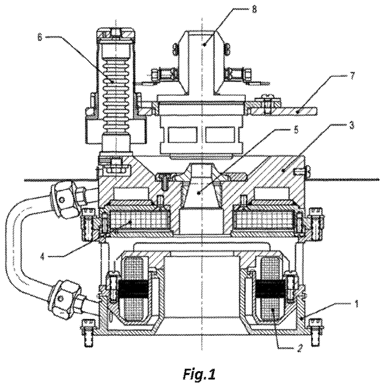
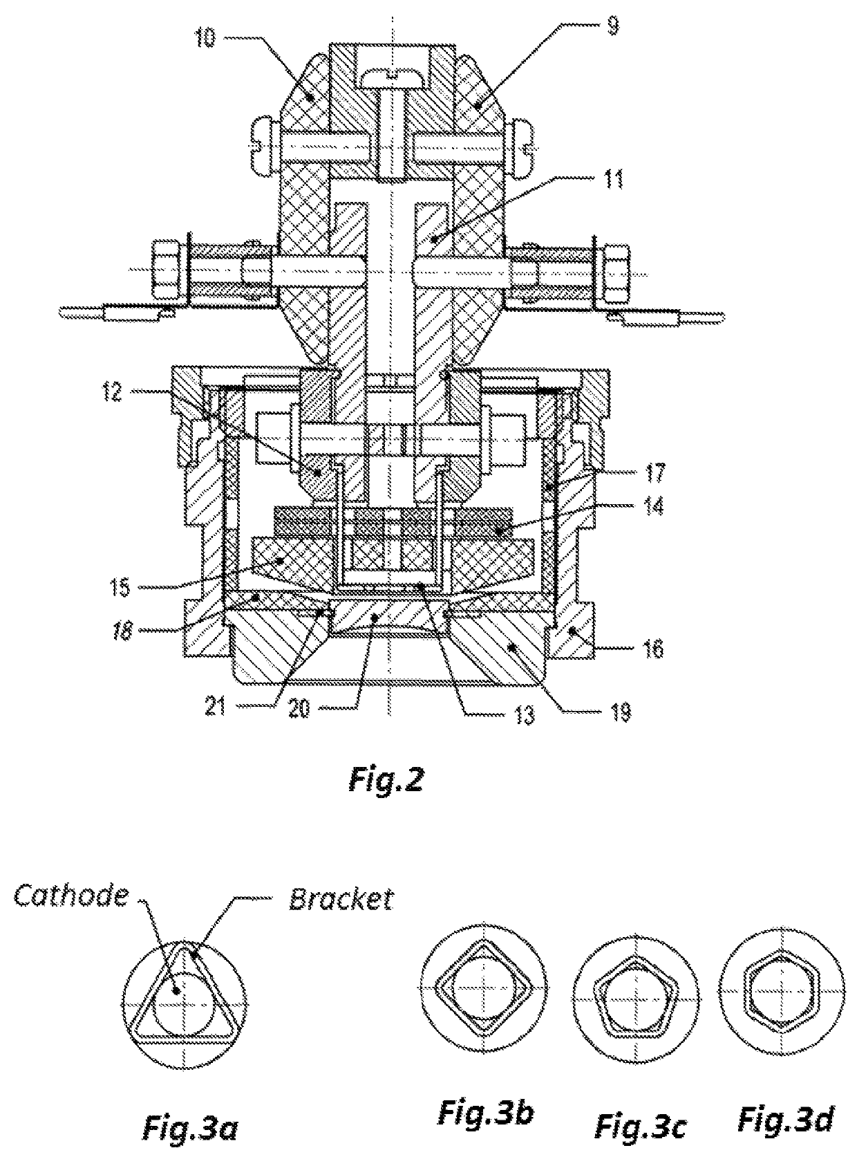
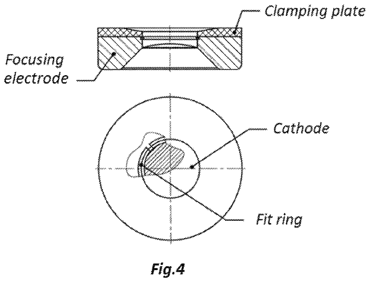
[0033]The axial electron gun (FIG. 1) comprising the cathode assembly (FIG. 2) operates as follows. Alternating voltage 4-10 VAC is applied to the current leads (11) so the heating current in the range 20 to 80 A runs through and heats the primary tungsten wire cathode (13). Bombarding voltage in the range −0.5 to −2.5 kV is applied between the primary cathode (13) and the secondary cathode (20). Electrons emitted from the primary cathode bombard and heat the secondary cathode to the temperature of about 2800° C. The intensity of heating of the secondary cathode (20) depends on the heating current of the primary cathode (13) and the bombarding voltage. Accelerating voltage in the range 18 to 30 kV is applied between the secondary cathode (20) fixed by the holder shaped as a plane regular polygon and the anode (5). Under effect of this voltage electrons leave the cathode (20), are focused by the focusing electrode (15) and run to the beam guide of the axial electr...


PUM

PropertyMeasurementUnit
diameteraaaaaaaaaa
pressureaaaaaaaaaa
pressureaaaaaaaaaa

Abstract

The invention relates to the field of fabrication of new materials and coatings and may be used in plants designed for electron-beam heating, melting and evaporating of materials in vacuum or reactive gas atmosphere. The disclosed axial electron gun that comprises, in particular, the primary and secondary cathodes and features the figure-shaped holder used for maintaining a stable position of the secondary cathode relative to the electron-beam axis of the axial gun and the pulsed voltage that is applied between the cathodes for electron bombardment of the secondary cathode. The invention ensures an improved stability of process parameters and operation of the electron gun.

Description

CROSS-REFERENCE TO RELATED APPLICATIONS[0001]This application is a 371 of PCT / UA2017 / 000064, filed Jun. 9, 2017, which claims benefit of Ukrainian Patent Application No. a 2016 09313 filed Sep. 7, 2016.TECHNICAL FIELD[0002]The invention herein is in the field of fabrication of new materials and coatings and relates to devices of the electron-beam technology in particular electron guns designed for electron-beam heating, melting and evaporating of materials in vacuum or reactive gas atmosphere.BACKGROUND OF THE INVENTION[0003]Electron guns with linear thermal cathode have been well known, in particular they were described in the patents for invention of Ukraine No. 21440A (B. A. Movchan, V. A. Timashov, Ye. L. Piiuk), No. 43927 (B. A. Movchan, O. Ya. Gavriliuk), No. 93182 (V. A. Timashov, O. L. Zhdanov, S. I. Ryabenko, A. A. Tsepkalov, S. Berns) and others. Their design features a beam guide, an accelerating anode and a cathode assembly that comprises a frame or cathode plate, insula...

Claims


Application Information

Patent Timeline
Patent Type & Authority Patents(United States)
IPC IPC(8): H01J37/065H01J1/18
CPCH01J37/065H01J1/18H01J37/075H01J1/26H01J1/20
Inventor TIMASHOV, VICTOR ALEXANDROVICHTSEPKALOV, ANDREY ANATOLYEVICHRYABENKO, SERGEY IVANOVICHBELYAVIN, ALEKSANDR FYODOROVICHMARYNSKIY, GEORGIY SERGEEVICHFILIPPOV, ALEKSEY VLADISLAVOVICH
Owner PATON TURBINE TECH LLC
Why Eureka
Try Eureka