Eureka AIR delivers breakthrough ideas for toughest innovation challenges, trusted by R&D personnel around the world.

Method to control a powertrain in a vehicle

a technology of powertrain and vehicle, applied in mechanical equipment, external condition input parameters, transportation and packaging, etc., can solve the problems of short time between successive upshifts and an increase in number of gear shifts, and increasing the risk of wheel spin, so as to increase the time between upshifts and limit acceleration, the effect of increasing the power shi

Active Publication Date: 2020-05-05
VOLVO LASTVAGNAR AB
View PDF22 Cites 0 Cited by
  • Summary
  • Abstract
  • Description
  • Claims
  • Application Information

AI Technical Summary

Benefits of technology

[0004]Vehicles provided with multi-clutch transmissions are provided with a controller that will control the operation of the clutch based on a gear strategy stored in the control unit. The gear shifting strategy may under certain circumstances select a skip shift, e.g. between two even gears, requiring the same clutch to be used. Skip up-shifts can be demanded in situations when powerful vehicle acceleration is performed. During an acceleration the engine speed after a power up-shift can be higher than or near the next up-shift speed, leading to a short time between successive upshifts and an increase in number of gear shifts. The skip shifts are used in order to avoid a series of rapid single up-shifts by shifting directly into a desirable lower gear ratio.
[0007]It is desirable to provide a method for controlling a multi-clutch transmission in a vehicle, which method allows skip up-shifts to be avoided during vehicle acceleration.
[0016]The predetermined time limit is preferably selected greater than the minimum time to perform a power shift. A longer time is selected to allow the transmission to run on each gear for a period of time to prevent excessive clutch slipping between consecutive clutch actuations and to avoid overheating of the clutches. A suitable predetermined time limit can be selected dependent on engine output power, vehicle size / load, clutch cooling capacity, or a similar suitable parameter. The predetermined time limit is also dependent on the time required by the transmission for preparing for the next power shift.
[0019]A reduction of the torque generated by the propulsion unit will reduce the input torque available to the multi-clutch transmission, thereby limiting the acceleration of the vehicle. The predetermined time limit is equal to the minimum time required for performing a power shift sequence. The control unit will use the prediction model comprising at least one simulated shift sequence for the multi-clutch transmission to calculate the output power reduction required to limit the vehicle acceleration so that the time between two sequential power upshifts is increased to be at least equal to the predetermined time limit.
[0026]The invention, according to an aspect thereof, has the advantages of improving driveability and providing a more constant acceleration, resulting in a more constant torque on the wheels and less risk for slipping.

Problems solved by technology

During an acceleration the engine speed after a power up-shift can be higher than or near the next up-shift speed, leading to a short time between successive upshifts and an increase in number of gear shifts.
However, skip shifts result in power cut-off gear changes which are less comfortable for the driver and may increase the risk of wheel spin.
This latter case will result in a longer time on the current gear due to the fact that the propulsion unit speed will be lowered immediately after the upshift.
However, it will also give lower comfort as a part of the torque will be reduced during the gearshift.
In all these cases the limitation of the acceleration will cause a delay to provide sufficient time for a power upshift, in order to avoid a skip shift.
When the propulsion unit comprises an internal combustion unit, the acceleration can be limited by injecting less fuel into the propulsion unit.
When the propulsion unit comprises a motor / generator, the acceleration is limited by reducing electric power to the propulsion unit.
Finally, when the powertrain comprises a hybrid electric propulsion unit, the acceleration is limited by driving an electric motor / generator using an internal combustion unit to regenerate energy.
A reduction of the torque generated by the propulsion unit will reduce the input torque available to the multi-clutch transmission, thereby limiting the acceleration of the vehicle.

Method used


Image

  • Method to control a powertrain in a vehicle
  • Method to control a powertrain in a vehicle
  • Method to control a powertrain in a vehicle

Examples


Embodiment Construction

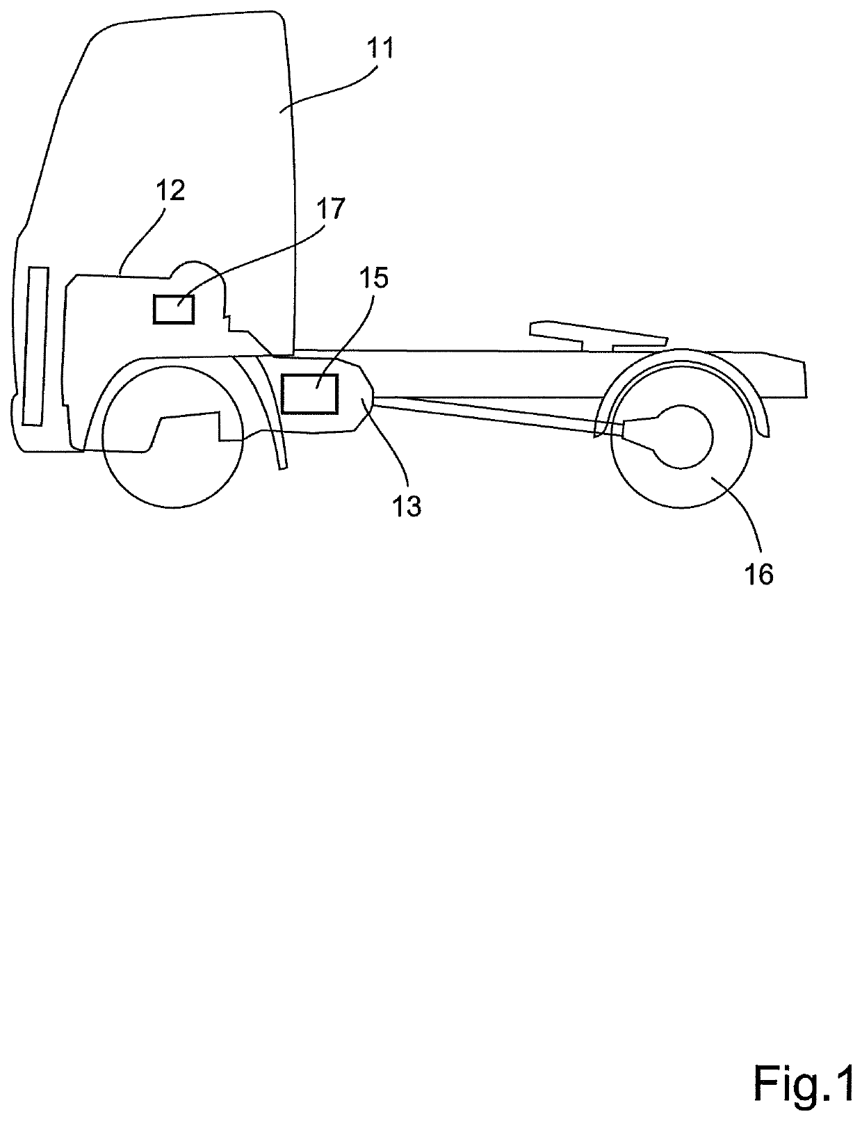
[0037]FIG. 1 shows a schematically indicated vehicle 11 with a transmission arrangement for use with a method according to an aspect of the invention. The vehicle 11 is provided with an internal combustion engine (ICE) 12 connected to a transmission 13 comprising a dual clutch arrangement 15, for transmitting torque to an output drive shaft (not shown). In the subsequent text this transmission will be referred to as a dual clutch transmission (DCT) 13. The ICE 12 is connected to a radiator arrangement 14 for cooling engine coolant and oil from the ICE 12 and the transmission 14. The transmission 13 is controlled by the driver or automatically via an electronic control unit (ECU) 17. The ECU 17 is provided with control algorithms for controlling the transmission independently during, for instance, an engine start requested by the driver. The transmission is controlled to select a gear ratio between the engine 12 and a pair of driven wheels 16.

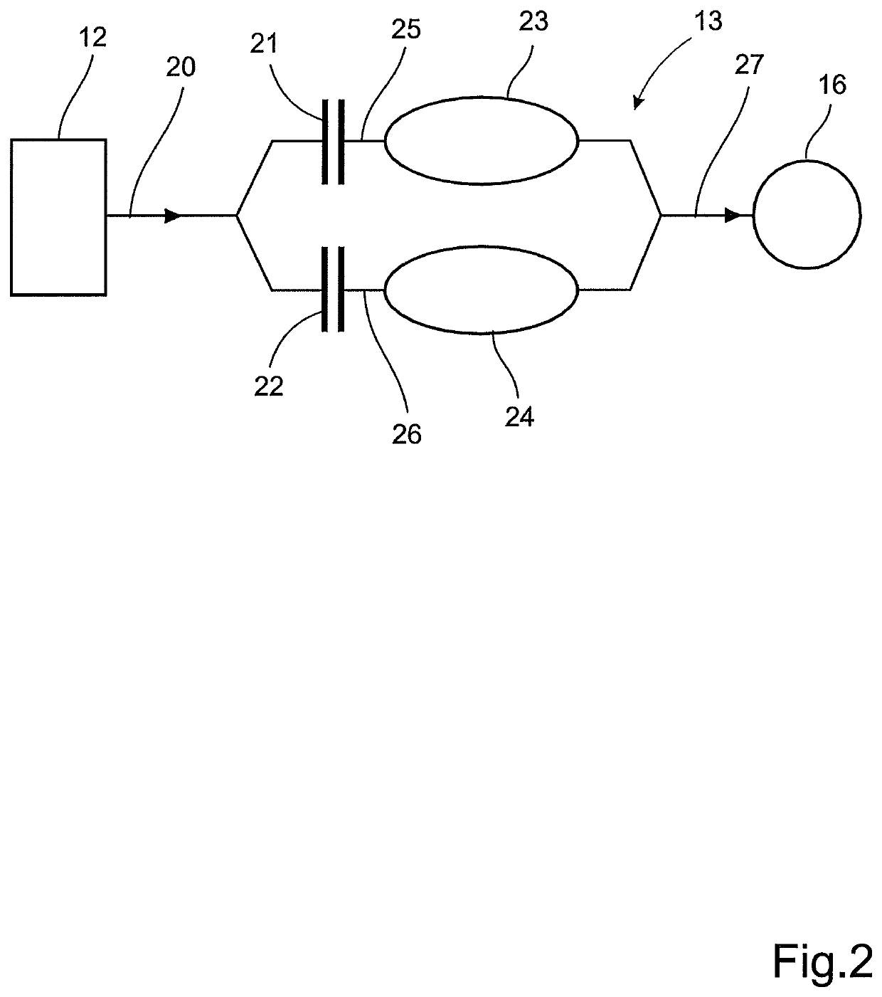
[0038]FIG. 2 shows a schematic, diagram o...


PUM


Abstract

A method to control a powertrain in a vehicle during an acceleration is provided, the powertrain including a propulsion unit, a multi-clutch transmission drivingly connected to the propulsion unit, and a control unit for controlling at least the powertrain components, which control unit is provided with a prediction model including at least one simulated shift sequence for the multi-clutch transmission. The method involves monitoring at least one operating parameter of the powertrain; estimating the time (tE) between initiation of a first power upshift and initiation of a sequential second power upshift using the prediction model; and, if the estimated time is shorter than a predetermined time limit (tLIM), controlling the propulsion unit to limit the vehicle acceleration so that the time between the first and second power upshifts is increased to be at least equal to the predetermined time limit (tLIM).

Description

BACKGROUND AND SUMMARY[0001]The invention relates to a method for controlling a powertrain in a vehicle during acceleration. The invention involves limiting the vehicle acceleration by controlling the powertrain if the estimated time between the two sequential power shifts is shorter than a predetermined time limit.[0002]The invention can be applied in heavy-duty vehicles, such as trucks, buses and construction equipment. Although the invention will be described with respect to a truck, the invention is not restricted to this particular vehicle, but may also be used in other vehicles such as buses, construction equipment and other work vehicles.[0003]Automatic and semi-automatic mechanical transmission systems for vehicles are well known in the prior art. Typically, such systems comprise a multi-speed mechanical change gear transmission, at least one friction clutch drivingly interposed the engine and the transmission and a central processing unit or controller for receiving input s...

Claims


Application Information

Patent Timeline
Patent Type & Authority Patents(United States)
IPC IPC(8): B60W30/19B60W30/18B60W10/08F16H61/02B60W20/15B60W10/06B60W10/113
CPCB60W30/19B60W10/06B60W20/15F16H61/0213B60W10/08B60W30/18B60W10/113B60W2720/106B60W2710/1005B60W2710/0627B60W2540/10B60W2510/0638Y10S903/93B60W2520/10B60Y2200/92B60W2710/083B60W2710/086B60W2552/00B60W2510/081B60W2710/0666F16H2061/0216Y02T10/62
Inventor KARLSSON, LARSBJERNETUN, JOHANERIKSSON, ANDERS
Owner VOLVO LASTVAGNAR AB
Why Eureka
Eureka Blog
Learn More