Multi-operational mode, method and system for operating a stormwater management (SWM) facility

a multi-operational, stormwater technology, applied in the direction of sewage draining, programme control, instruments, etc., can solve the problems of discouraged flow paths between inflow and outflow points of swm facilities, and achieve the effect of improving the performance of existing stormwater management facilities

Active Publication Date: 2020-05-05
CENTURY ENG LLC
View PDF8 Cites 2 Cited by
  • Summary
  • Abstract
  • Description
  • Claims
  • Application Information

AI Technical Summary

Benefits of technology

[0016]Furthermore, the present invention, SmartSWM, is designed to function off the grid [via solar power], but can also be installed using local line power. Additionally,

Problems solved by technology

Consequently, SWM facility designs that allow for “short circuit” fl

Method used


Image

  • Multi-operational mode, method and system for operating a stormwater management (SWM) facility
  • Multi-operational mode, method and system for operating a stormwater management (SWM) facility

Examples


Embodiment Construction

[0020]Before explaining at least one embodiment of the present invention in detail, it is to be understood that the invention is not limited in its application to the details of construction and to the arrangements of the components set forth in the following description or illustrated in the drawings. The invention is capable of other embodiments and of being practiced and carried out in various ways. Also, it is to be understood that the phraseology and terminology employed herein are for the purpose of description and should not be regarded as limiting.

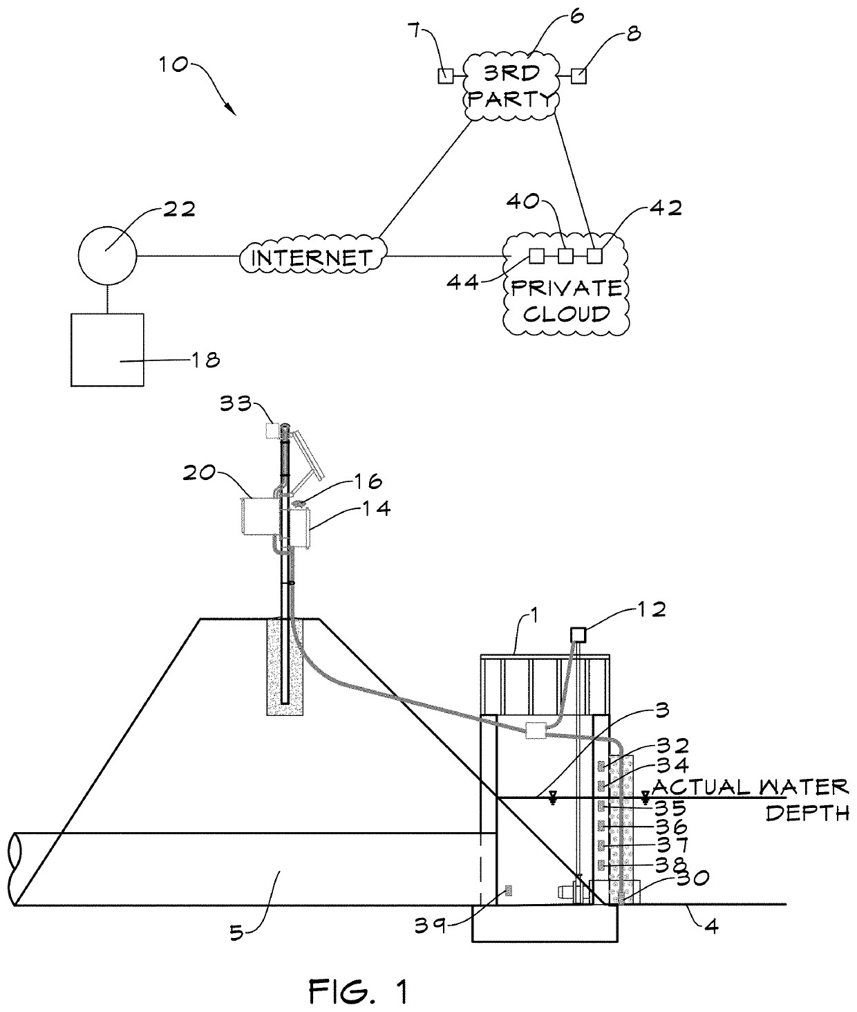
[0021]Recognizing the need for improvements in the means for controlling the operation of SWM facilities, there is illustrated in FIG. 1 a preferred embodiment of the present invention 10 in the form of a SmartSWM system or method.

[0022]FIG. 1 shows a generalized version of a SWM facility 1 which is holding stormwater 2 whose free surface 3 is at a measurable depth, d, above the bottom 4 of the SWM facility and an outflow conduit 5...


PUM


Abstract

The present invention presents both a method and system for controlling a stormwater management facility to operate in any one of a plurality of operational modes, each of which has differing environmental benefits resulting from its treatment of the stormwater that passes through the facility. A preferred embodiment of this system includes: an actuated control valve, a depth sensor, a valve controller that has internet connectivity and sensor interfaces and a user input means, controller software configured to control the operation of the control valve to operate in one of its plurality of operating modes, and private-cloud-based, internet-accessible, engine software that is configured to utilize weather forecasts to calculate a temporally-varying, targeted depth for the stormwater in the facility that maximizes the volume of stormwater treated in the SWM facility.

Description

BACKGROUND OF THE INVENTION1. Field of the Invention[0001]The present invention relates generally to the management of stormwater facilities that seek to control urban stormwater runoff. More particularly, the present invention relates to systems and methods for operating a stormwater facility in any one of a plurality of operational modes to yield various environmental benefits.2. Description of the Related Art[0002]Since at least 1972, the United States Environmental Protection Agency (USEPA) has been investigating the causes of and solutions for the nation's water pollution problems. Urban stormwater runoff due to storms or precipitation events has been identified as a significant contributor to this problem since stormwater carries with it pollutants such as bacteria, heat, phosphorus, nitrogen, and sediment. Collectively these pollutants have been identified as significant contributors to the decline of the health of the natural streams and other natural bodies of water into wh...

Claims


Application Information

Patent Timeline
IPC IPC(8): E03F1/00G05B19/042
CPCG05B19/042E03F1/00E03F5/107
Inventor BATHURST, ROBERT G.
Owner CENTURY ENG LLC
Why Eureka
Try Eureka