Thermally-assisted magnetic recording head having optimal reflecting position inside waveguide

a technology of magnetic recording head and waveguide, which is applied in the direction of maintaining head carrier alignment, light beam reproducing, instruments, etc., can solve the problems of unstable optical power of laser diodes and unstable recording characteristics of thermally assisted magnetic heads

Active Publication Date: 2020-05-12
SAE MAGNETICS (HK) LTD
View PDF10 Cites 1 Cited by
  • Summary
  • Abstract
  • Description
  • Claims
  • Application Information

AI Technical Summary

Benefits of technology

[0017]On the other hand, when the reflecting-position of the laser light is shifted, it brings shifting an interference pattern of laser light. Therefore, if the reflecting-position, of laser light in inside of the waveguide, is shifted, wavelength dependence of optical feedback change, thereby there is a possibility that unstableness of optical power is lowered.
[0018]However, the effective suggestion, concerning the optimal reflecting-position in inside of the waveguide, is not conventionally known, on the viewpoint that unstableness of optical power caused by the mode-hopping is lowered.

Problems solved by technology

There is a following problem in the thermally assisted magnetic head, having the above-described conventional structure.
The problem is caused by optical feedback of a laser diode.
In this case, standing wave conditions collapse by mixing optical feedback, in the laser diode, unstable action, which is called “mode hopping”, which oscillation wavelength change suddenly, is caused.
Thereby, optical power of the laser diode become unstable.
Then, a recording characteristic of the thermally assisted magnetic head becomes unstable.

Method used


Image

  • Thermally-assisted magnetic recording head having optimal reflecting position inside waveguide
  • Thermally-assisted magnetic recording head having optimal reflecting position inside waveguide
  • Thermally-assisted magnetic recording head having optimal reflecting position inside waveguide

Examples


Embodiment Construction

[0050]In the following, embodiments of the present invention will be described with reference to the drawings. Note that the same components will be referred to with the same numerals or letters, while omitting their overlapping descriptions.

[0051](Structure of the Thermally Assisted Magnetic Head)

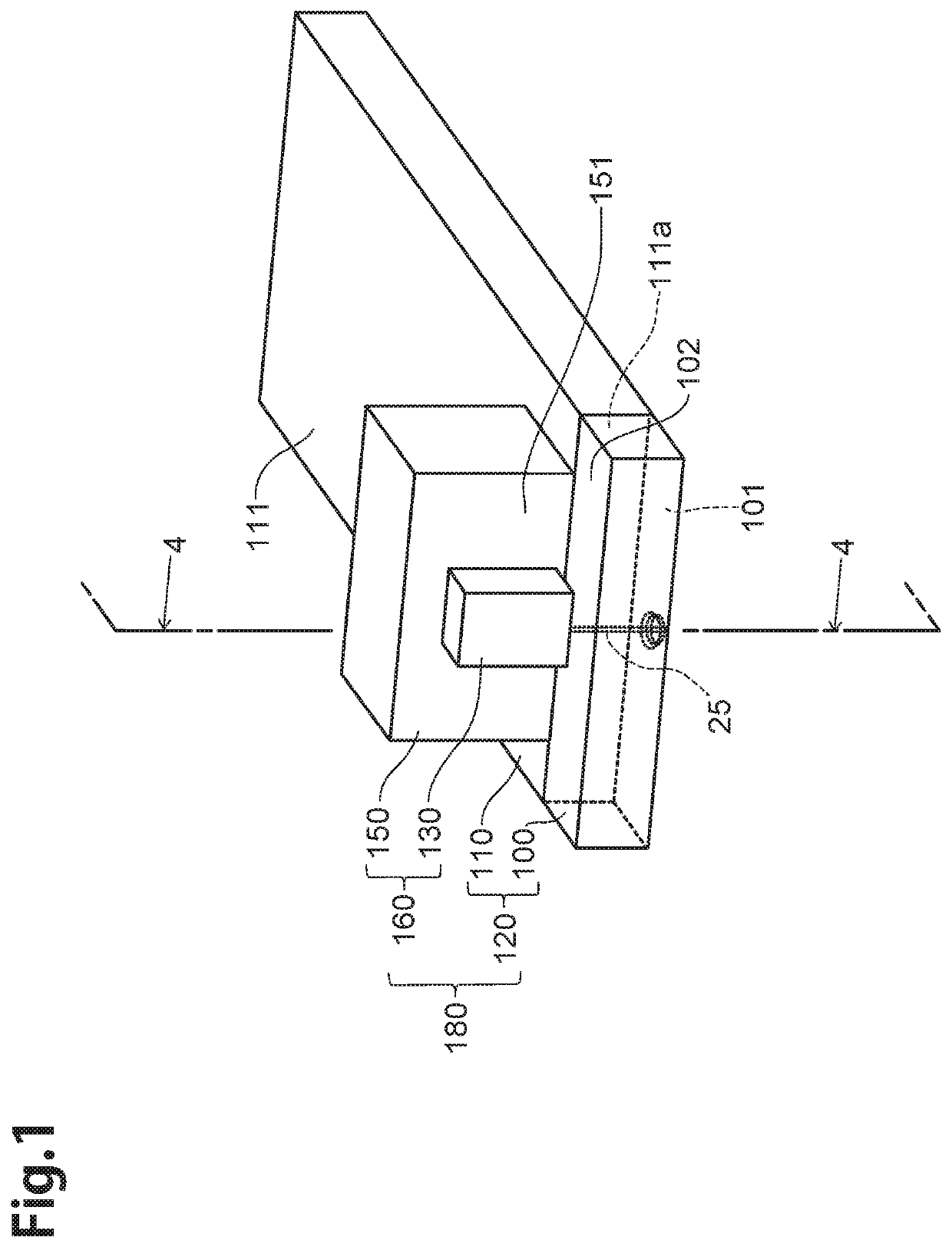
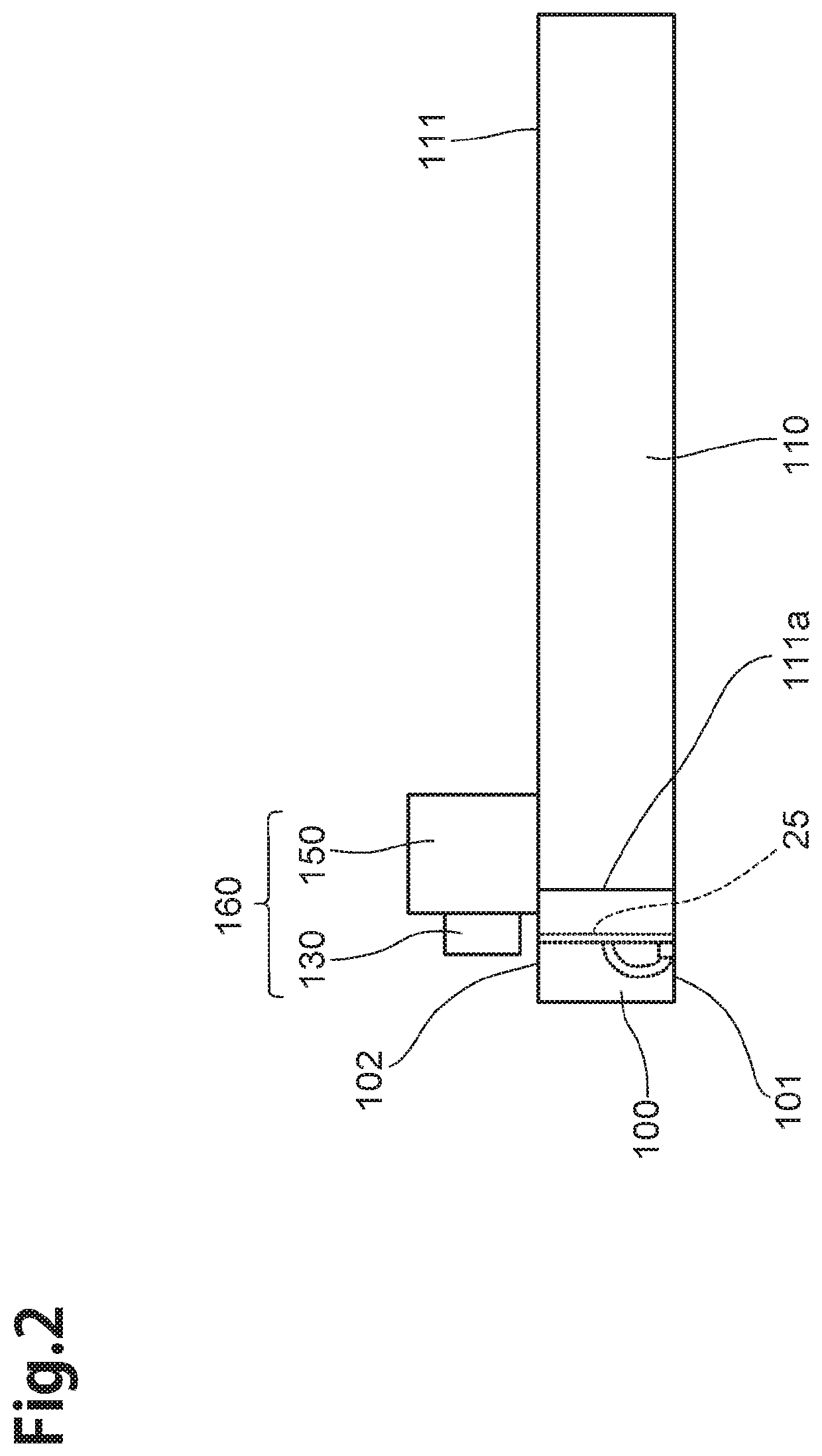
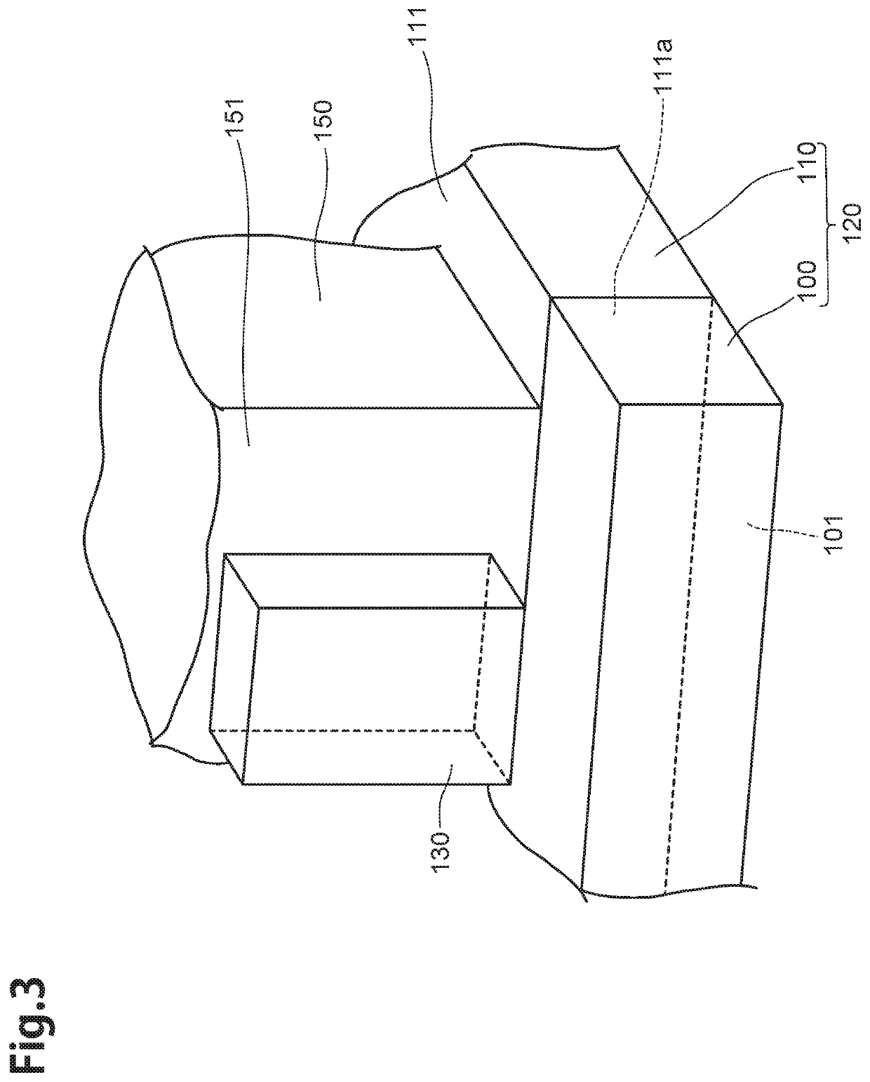
[0052]To begin with, structure of the thermally assisted magnetic head according to the embodiment of the present invention will be explained with reference to FIG. 1 to FIG. 5. Here, FIG. 1 is a perspective view of the thermally assisted magnetic head 180 according to the embodiment of the present invention, FIG. 2 is a side view of the thermally assisted magnetic head 180 according to the embodiment of the present invention, FIG. 3 is a perspective view, with enlargement, of the principal part of the thermally assisted magnetic head 180. FIG. 4 is a sectional view of principal part taken along the line 4-4 in FIG. 1, FIG. 5 is a front view, partially omitted, illustrating a medium-opposi...


PUM

PropertyMeasurementUnit
inlet-optical path length L1aaaaaaaaaa
outlet-optical path length L2aaaaaaaaaa
optical path length L1aaaaaaaaaa

Abstract

A thermally assisted magnetic head including a slider and a light source-unit. The slider includes a slider substrate and a magnetic head part. The light source-unit includes a laser diode and a sub-mount. The magnetic head part includes a medium-opposing surface, a light source-opposing surface and a waveguide which guides laser light from the light source-opposing surface to the medium-opposing surface. The thermally assisted magnetic head includes an optimal-structure which the following optimizing conditional expression, concerning an inlet-optical path length L1 of an inlet-interval of the waveguide, and an outlet-optical path length L2 of an outlet-interval, is satisfied,m1×L1=L2 (m1 is a natural number).

Description

BACKGROUNDField of the Invention[0001]The present invention relates to a thermally assisted magnetic head recording data on a magnetic recording medium by thermally assisted magnetic recording using near-field light, a head gimbal assembly and a hard disk drive each having the thermally assisted magnetic head.Related Background Art[0002]In recent years, as magnetic disk drives have been increasing their recording densities, thin-film magnetic heads recording data on a magnetic recording media have been required to further improve their performances. As the thin-film magnetic heads, those of composite type having a structure in which a reproducing head having a magnetoresistive device (hereinafter, referred to also as an “MR device”) for read and a recording head having an electromagnetic coil device for write are laminated have been conventionally in wide use. In a magnetic disk drive, the thin-film magnetic head is provided on a slider which very slightly floats from the magnetic r...

Claims


Application Information

Patent Timeline
Patent Type & Authority Patents(United States)
IPC IPC(8): G11B11/105G11B13/04G11B5/48G11B5/00G11B11/24G11B5/60G11B13/08
CPCG11B5/4826G11B13/04G11B2005/0021G11B11/24G11B5/6088G11B13/08
Inventor HOSOI, RYOTAKAYAMA, SEIICHI
Owner SAE MAGNETICS (HK) LTD
Why Eureka
Try Eureka