Multimode communication method for transmission line condition monitoring

a transmission line and communication method technology, applied in data switching networks, instruments, high-level techniques, etc., can solve the problems of lack of resistance, limited application of this technology, and large losses to the power grid, and achieve the effect of prolonging the service life of the whole network

Active Publication Date: 2020-05-12
JIANGSU ELECTRIC POWER CO +1
View PDF11 Cites 2 Cited by
  • Summary
  • Abstract
  • Description
  • Claims
  • Application Information

AI Technical Summary

Benefits of technology

[0015]In order to solve deficiencies in existing technologies, this patent proposes a multi-mode communication method to balance energy consumption of communication network nodes, which can prolong service life of the whole network.
[0023]The beneficial effect of this patent is: (1) The patent integrates ZigBee technology and Bluetooth technology to transmit status signal data of power transmission line, which can integrate ZigBee technology and Bluetooth 4.0 technology according to requirements of the size and the security of transmitting data. This patent design a method to automatic choose communication network between sensing nodes that monitor status signal data of power transmission line and corresponding forwarding devices as well as adaptive multi-mode communication mode selection. So, this method can effectively remedy the limitation of single communication technology, which enhances the level of status signal data of power transmission line monitoring. (2) This patent relates to a forwarding device selection mechanism based on multi parameters. Considering limitation of energy consumption factors and particularity of status signal data of power transmission line monitoring, this patent proposes a multi parameter forwarding device selection mechanism to ensure reasonable energy consumption of each sensing device and prevent sensing devices from consuming too much energy even stopping work because of forwarding data and, so as to balance node energy consumption and prolong service life of the whole network.
[0028]The patent relates to a method for solving transmission conflicts based on data priority, focuses on forwarding device selection mechanism based on multi parameter and proposes a method to solve data transmission conflict based on data priority. This method can effectively solve the problem of data transmission conflict, ensure reliable data transmission and improve transmission quality.

Problems solved by technology

However, long distance transmission wires are basically exposed to the outside, which is vulnerable to be affected by climate, geology and human factors.
The pollution flashover, lightning stroke, wire icing and galloping caused huge losses to power grid.
Traditional Bluetooth technology is affected by transmission distance, power consumption and other factors, so application of this technology is limited.
(1) ZigBee technology also has limitations, such as application of this technology is limited due to low data transmission rate. Although direct sequence spread spectrum technology is used to reduce the loss, this method is lack of ability to resist interference. In addition, the 2.4 GHz band provides less working channel and is easy to cause interference and conflict between nodes.
(2) Compared with ZigBee Technology, Bluetooth 4.0 technology also has its own limitations, such as support less topology structure, single network mode, unsupported mesh networking, low robustness and less accommodating node.
Moreover, energy consumption is one of the main factors that restrict short distance wireless communication technology.
However, the idea of clustering is not suitable for monitoring status data of power transmission line.
However, few nodes monitor the same object along one power transmission line and distribution of nodes is more dispersed, which is not suitable for clustering.
Nodes that the closer to sink node, the more energy consumed by forwarding too much, which leads to these nodes stop working because of energy exhaustion.
At the same time, it is easy to receive multiple forwarding requests in one data forwarding process and trigger forwarding conflict, which cannot guarantee the quality of data transmission and cause low data transmission rate.

Method used


Image

  • Multimode communication method for transmission line condition monitoring

Examples


implementation example

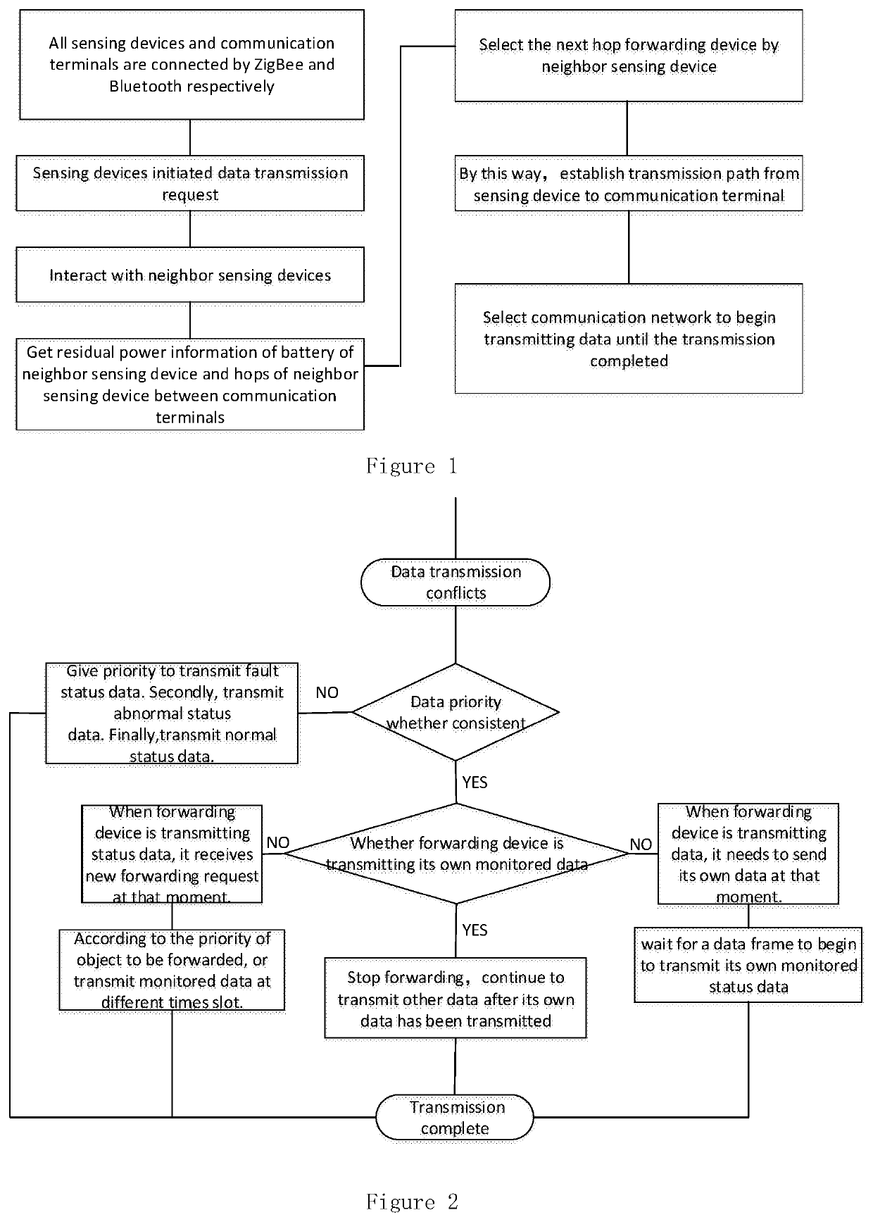
[0032]In this implementation example, sensing devices are built on power transmission line to detect status signals of that. These status signals are sent to remote monitoring center through communication terminals. Both sensing devices and communication terminals are powered by battery. The sensing device comprises processor module, Bluetooth 4.0 module, ZigBee module, sensor module and power supply module. Among them, sensor module is responsible for sensing status data of power transmission line (including temperature, wind, tension, contamination and other information) and use for generating status data signal of power transmission line. The communication terminal comprises antenna module, ZigBee module, Bluetooth 4 module, WinMax module, processor module and power supply module. ZigBee module and Bluetooth 4 module are used to meet communication hardware requirements between communication terminal and sensing device. The Win-Max module is responsible for transmitting status dat...


PUM


Abstract

This patent relates to a multi-mode communication method for detecting states of power transmission line, which belongs to electric power communication technology field. In this method, there are sensing devices installed on power transmission line. These sensing devices are used to detect status signals of power transmission line. Status signals are sent to remote monitoring center through communication terminals. Both sensing devices and communication terminals are powered by battery. The main communication network between sensing devices and communication terminals is formed by ZigBee network. Meanwhile, Bluetooth network is a backup communication network between sensing devices and communication terminals. Communication terminals and remote monitoring center are linked through WinMAX. This method can take full advantage of these two short-range wireless communication technologies and break limitations of a single technology, ensure reasonable energy consumption, improve efficiency and quality of data transmission.

Description

CROSS REFERENCE TO RELATED APPLICATION[0001]This application is a National Phase application of, and claims priority to, PCT Application No. PCT / CN2016 / 080846, filed on Apr. 29, 2016 entitled “Multimode Communication Method for Transmission Line Condition Monitoring,” which claims priority to Chinese Application No. 201610143210.5, filed on Mar. 14, 2016. Both the PCT Application and Chinese Application are incorporated herein by reference in their entireties.TECHNOLOGY FIELD[0002]The patent relates to a multi-mode communication method for Power transmission line state monitoring, belongs to electric communication technology field of digital information transmission.BACKGROUND TECHNOLOGY[0003]Power transmission line is an important part of power system, it is the artery of electric power system. However, long distance transmission wires are basically exposed to the outside, which is vulnerable to be affected by climate, geology and human factors. The pollution flashover, lightning s...

Claims


Application Information

Patent Timeline
Patent Type & Authority Patents(United States)
IPC IPC(8): H04W4/80G01R31/387H04W40/10H04L12/707H04W40/22H04L12/703H04L12/733H04W40/12G08C17/00H04W84/18H04B1/713H04L45/122H04L45/24H04L45/28H04L47/6275
CPCH04W40/12H04W40/10H04W40/22H04W4/80H04L45/28G01R31/387G08C17/00H04L45/22H04L45/122Y02D70/162Y02D70/14Y02D70/40Y02D70/144H04B1/713Y02D70/10H04W84/18Y02D70/22H04L47/6275Y02D30/70
Inventor WEI, LEILU, MINSHAO, MINGCHIXU, WEILI, QIUSHENGGUO, CHUANGCHEN, DIANXINYAN, DONGJIANG, LING
Owner JIANGSU ELECTRIC POWER CO
Why Eureka
Try Eureka