
Ultra-broadband microwave radiometer optimized for microsatellite applications

a microwave radiometer and ultra-broadband technology, applied in the field of micro-wave radiometers, can solve the problems of limited typical cubesat microwave radiometers, unacceptable harmonic rejection and phase noise, and previously available cubesat microwave radiometers that do not have a wide band tuning range, so as to reduce volume, mass, phase noise and power requirements, and increase harmonic rejection

Active Publication Date: 2020-05-19
NASA
View PDF4 Cites 1 Cited by
  • Summary
  • Abstract
  • Description
  • Claims
  • Application Information

AI Technical Summary

Benefits of technology

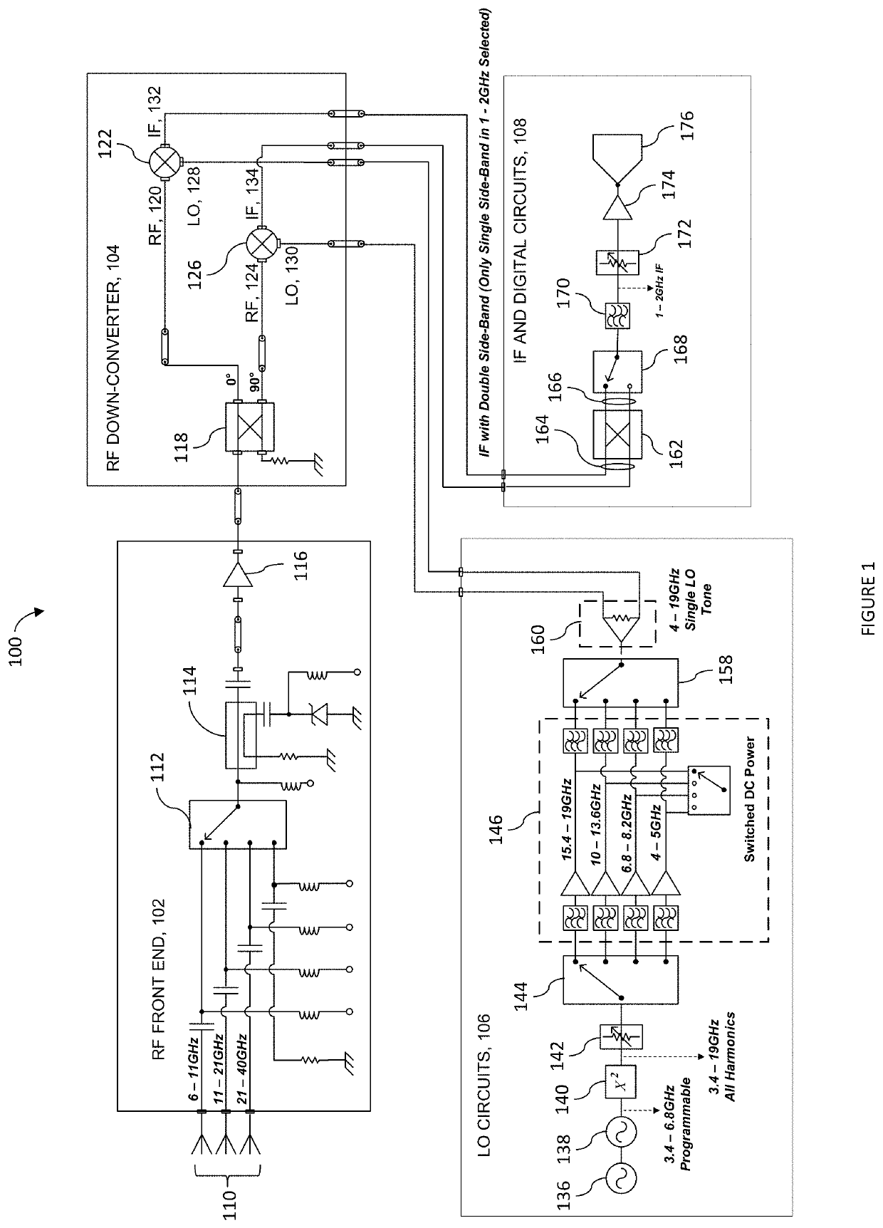
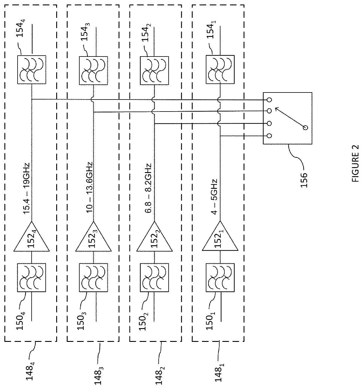
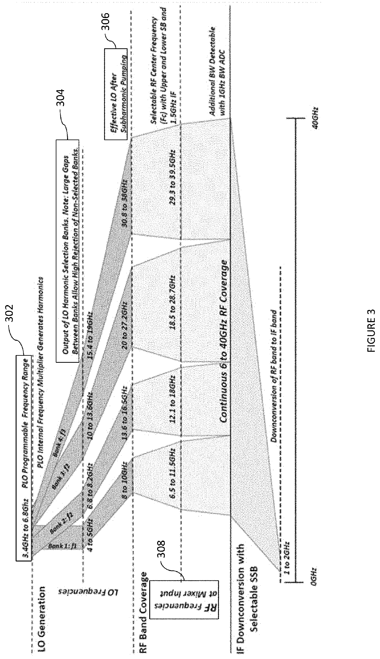
The patent describes a microwave radiometer that has reduced size, mass, phase noise, and power requirements while also increasing harmonic rejection. The radiometer includes a fixed number of frequency banks that provide signals within separate, non-overlapping local oscillation frequency bands. A detection circuit detects microwave RF signals, and an RF downconverter mixes the signals with the separate, non-overlapping local oscillation frequency bands to provide a continuous range of down converted frequencies. The radiometer also includes a comb generator and a switched power circuit for selectively powering amplifiers of individual frequency banks. The method of detecting microwave emissions utilizing the radiometer includes configuring the fixed number of frequency banks, detecting the microwave RF signals, and using a sub-harmonic mixer to double the signals within the separate, non-overlapping local oscillation frequency bands. The method also includes generating an upper and lower sideband down converted signal, and converting one of the signals to a digital format using an A / D converter. The technical effects of the patent include reducing the size and power requirements of the microwave radiometer while also increasing harmonic rejection.

Problems solved by technology

While there have been microwave radiometers designed to CubeStat specifications, previously available CubeSat microwave radiometers are not known to have a wide band tuning range and acceptable harmonic rejection and phase noise.
Typical CubeSat microwave radiometers are usually limited to discrete frequencies for measuring specific atmospheric characteristics.

Method used


Image

  • Ultra-broadband microwave radiometer optimized for microsatellite applications
  • Ultra-broadband microwave radiometer optimized for microsatellite applications
  • Ultra-broadband microwave radiometer optimized for microsatellite applications

Examples


Embodiment Construction

[0030]The disclosed embodiments uniquely combine several technologies to achieve mass, volume, and power requirement reductions while providing continuous radio frequency (RF) frequency coverage, high local oscillator (LO) harmonic rejection, high LO RF power and low LO phase noise. The disclosed embodiments generally include a sub-harmonically pumped mixer, an upper-lower side-band-select switch, wide-band analog-to-digital converters for intermediate frequency (IF) sampling, a broad-band frequency synthesizer used as a comb generator, and selectively powered frequency selection banks for a local oscillator. While the disclosed embodiments are described as operating from 6-40 GHz with an IF of 1-2 GHz, it should be understood that these ranges are exemplary, and that the disclosed embodiments may operate at any frequencies suitable for microwave radiometry within limitations of the component parts. Furthermore, it should be understood that the disclosed embodiments are not limited ...


PUM


Abstract

A microwave radiometer with reduced volume, mass, phase noise, and power requirements and increased harmonic rejection, includes a fixed number of frequency banks configured to provide signals within separate, non-overlapping local oscillation frequency bands, a detection circuit configured to detect one or more microwave RF signals, and an RF downconverter configured to mix the signals within the separate, non-overlapping local oscillation frequency bands with the one or more microwave RF signals to provide a continuous range of down converted frequencies.

Description

ORIGIN OF THE INVENTIONInvention by Government Employee(s) Only[0001]The invention described herein was made by an employee of the United States Government, and may be manufactured and used by or for the Government for governmental purposes without the payment of any royalties thereon or therefor.BACKGROUNDField[0002]The aspects of the present disclosure relate generally to a microwave radiometer, in particular to a microwave radiometer suitable for use in CubeSat applications.Description of Related Art[0003]A CubeSat is a small satellite having dimensions based on a standard CubeSat unit (U) of a 10 cm cube, with a mass equal to or less than approximately 1.33 kg, and specific energy consumption and generation constraints. Typical sizes include 1.5 U, 2 U, 3 U, and 6 U, with additional sizes being developed. The small sizes, and standardization of sizes, masses, and energy constraints has made it cost effective to provide mass produced, off the shelf components and have also result...

Claims


Application Information

Patent Timeline
Patent Type & Authority Patents(United States)
IPC IPC(8): H04B1/16H04B1/00H04B7/185H04B1/18
CPCH04B1/0028H04B1/1638H04B1/18H04B7/18515H04B1/1615H04B1/006
Inventor KNUBLE, JOSEPHPIEPMEIER, JEFFREYHORGAN, KEVINLUCEY, JARED
Owner NASA
Learn More