Digital isolator module for high level common mode transient immunity

Active Publication Date: 2020-05-19
AMAZING MICROELECTRONICS
View PDF9 Cites 4 Cited by
  • Summary
  • Abstract
  • Description
  • Claims
  • Application Information

AI Technical Summary

Benefits of technology

[0006]In order to overcome the above mentioned disadvantages, one major objective in accordance with the present invention is provided for a novel and creative isolat

Problems solved by technology

Nevertheless, transmission errors always occur due to a transient common noise VGND generated between these two ground voltages Vss1 and Vss2.
Also, since the conventional RX scheme circuits are not designed to be able to afford and tolerate high VGND voltages, the signal transmission has inevitably gone wrong owing to such the transient common noise, and the performance of the isolation circuit to convey signals suffers a lot due to common mode current transients.
However, it was observed that its data transmission process encounters propaga

Method used


Image

  • Digital isolator module for high level common mode transient immunity
  • Digital isolator module for high level common mode transient immunity
  • Digital isolator module for high level common mode transient immunity

Examples


Embodiment Construction

[0034]Reference will now be made in detail to the preferred embodiments of the present invention, examples of which are illustrated in the accompanying drawings. Wherever possible, the same reference numbers are used in the drawings and the description to refer to the same or like parts.

[0035]The embodiments described below are illustrated to demonstrate the technical contents and characteristics of the present invention and to enable the persons skilled in the art to understand, make, and use the present invention. However, it shall be noticed that, it is not intended to limit the scope of the present invention. Therefore, any equivalent modification or variation according to the spirit of the present invention is to be also included within the scope of the present invention.

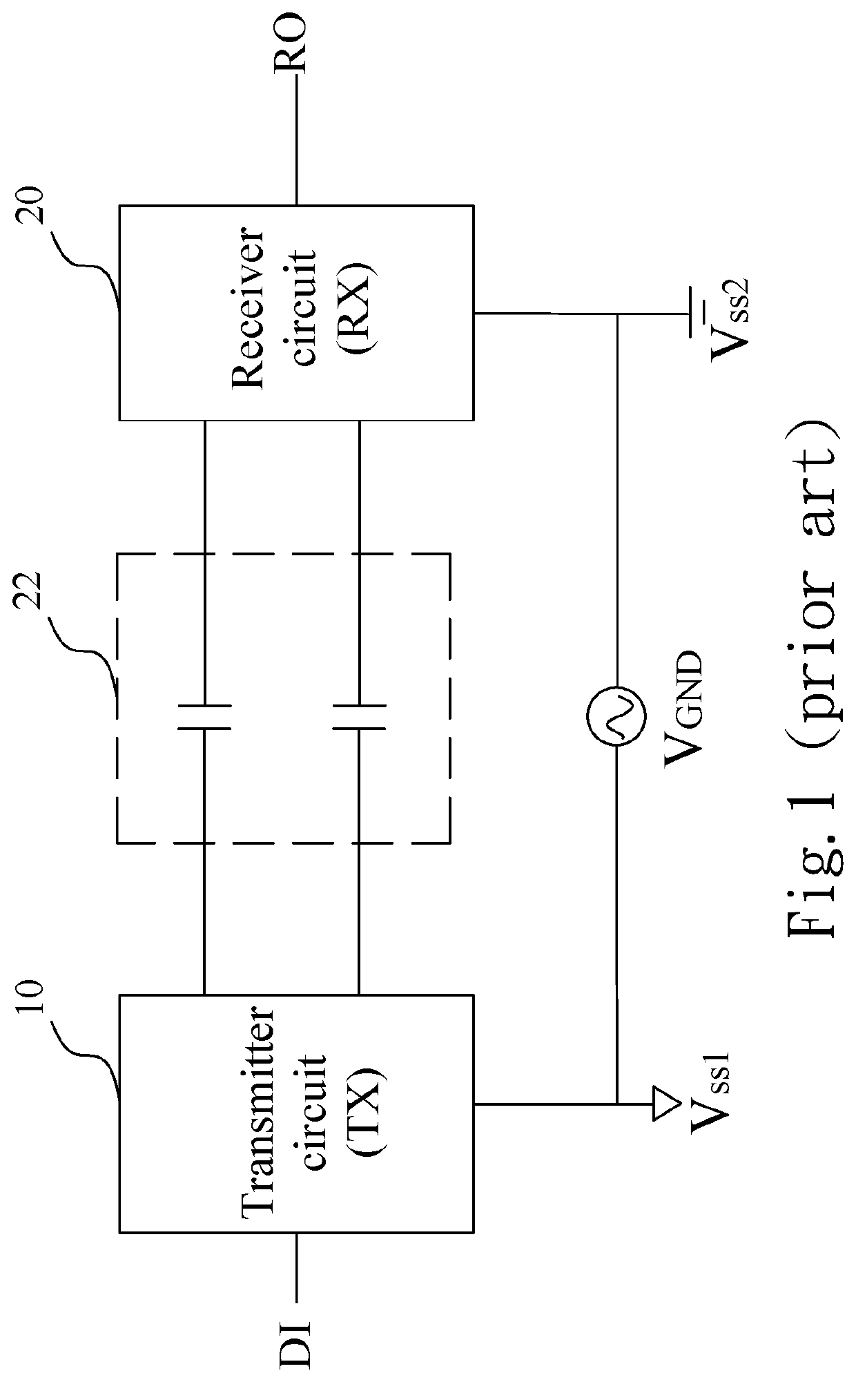
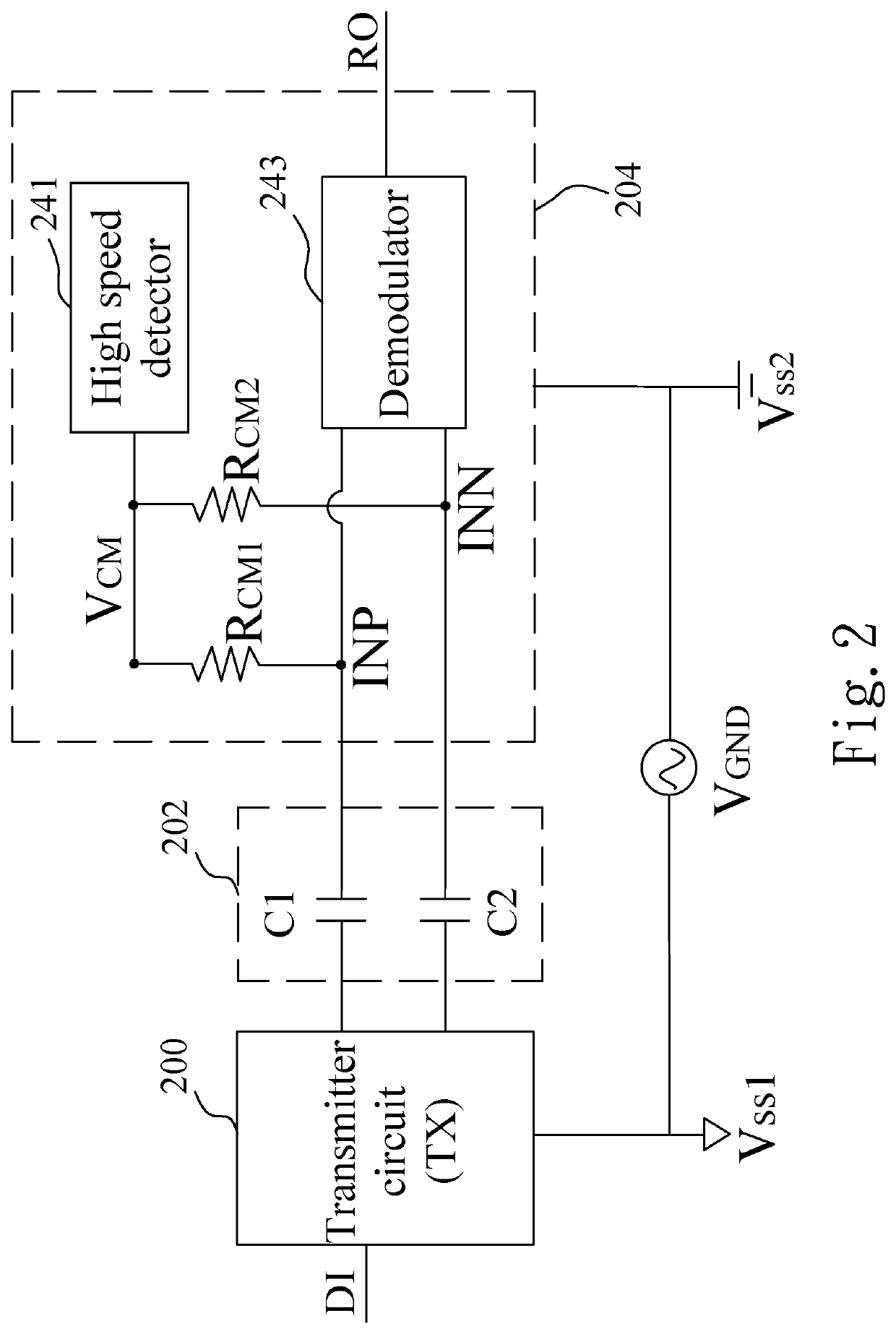
[0036]Please refer to FIG. 2, which shows a block diagram of a digital isolator module for high level common mode transient immunity in accordance with one embodiment of the present invention. As shown in FIG. ...


PUM


Abstract

A digital isolator module for high level common mode transient immunity is provided, comprising a transmitter circuit (TX), a receiver circuit (RX) and an isolation barrier which is connected there in between, wherein the transmitter circuit is electrically connected to a first ground voltage level and the receiver circuit is electrically connected to a second ground voltage level. The receiver circuit further comprises a resistance set, a high speed detector and a demodulator. By employing the proposed circuit diagram of the invention, interferences occurring at the common mode are suppressed and an RX output signal is synchronized with its input signal without having propagation delay.

Description

BACKGROUND OF THE INVENTIONField of the Invention[0001]The present invention is related to an isolation circuit, and more particularly to a digital isolator module which is employed for high level common mode transient immunity while ensuring reliable data transmission without propagation delay.Description of the Prior Art[0002]As we know, isolation circuits are the interface circuits that provide galvanic isolation between two communicating blocks, for example, a transmitter circuit (TX) and a receiver circuit (RX). Such isolation circuits are required to eliminate avoidable ground loops, and also to protect high voltage sensitive circuits. These circuits ensure electric insulation and signal isolation between the circuits, ensuring reliable data transmission between the two circuits, isolating the signal from fast transient common mode noise. In applications where common mode noise can be expected and human interactions are inevitable (e.g., cardiograph), then the isolation circui...

Claims


Application Information

Patent Timeline
IPC IPC(8): H04B1/40H04B15/02
CPCH04B15/02H04B1/40H03K19/017509H03K19/00346
Inventor LI, GUAN-SHUNWU, SZU-HSIEN
Owner AMAZING MICROELECTRONICS
Why Eureka
Try Eureka