Flowline junction fittings for frac systems

a flowline and junction fitting technology, applied in the direction of branching pipes, mechanical equipment, wellbore/well accessories, etc., can solve the problems of limited porousness of shale rock, limestone and coal beds, and inability to easily flow hydrocarbons, etc., to achieve the effect of reducing the cost of production

Active Publication Date: 2020-05-26
KHOLLE MAGNOLIA 2015 LLC
View PDF21 Cites 74 Cited by
  • Summary
  • Abstract
  • Description
  • Claims
  • Application Information

AI Technical Summary

Benefits of technology

[0053]Additional embodiments provide such frac manifolds where the missile comprises junction fittings having a generally cylindrical body. The mounts comprise a pedestal and a cradle. The mounts are coupled to the frame. The cradles are adapted to receive the junction fittings and to restrict transverse movement of the junction fittings.

Problems solved by technology

Hydrocarbons, however, are not always able to flow easily from a formation to a well.
Other formations, however, such as shale rock, limestone, and coal beds, are only minimally porous.
The formation may contain large quantities of hydrocarbons, but production through a conventional well may not be commercially practical because hydrocarbons flow though the formation and collect in the well at very low rates.
Pressure builds rapidly to the point where the formation fails and begins to fracture.
Continued pumping of fluid into the formation will tend to cause the initial fractures to widen and extend further away from the wellbore, creating flow paths to the well.
Systems for successfully completing a fracturing operation, therefore, are extensive and complex, as may be appreciated from FIG. 1. FIG. 1 illustrates schematically a common, conventional frac system.
Assembly of so many units on site can be time consuming, expensive, and hazardous.
Providing all those flow lines and manifolds on a trailer which meets highway regulatory requirements often results in a complex, cluttered design which may be difficult or impossible to service on site.
Trailered and skidded units can be quite large, heavy, and moveable only with difficulty and limited precision.
In part that is unavoidable.
The net result is that a fracking system often is so complicated that it resembles to the uninitiated a tangled mass of spaghetti.
Fracturing a horizontal well, however, may require fracturing in 20 or more zones.
Given the high number of components, leaking at unions is always a concern in frac systems.
The unions may not always be assembled properly.
Even when assembled to specification, however, such issues are exacerbated by the extremely high pressures and flow rates through the system.
Many unions also incorporate elastomeric seals which are exposed to flow through the conduit and are particularly susceptible to leaking.
Moreover, the abrasive and corrosive nature of the slurry flowing through a frac system not only will accelerate deterioration of exposed elastomeric seals, it can rapidly erode and weaken conduit walls.
Flow through other areas, however, such as unions where exposed seals often are present, may be quite turbulent.
Erosion also is a more significant issue where a flow line changes direction.
The flowlines in conventional frac manifolds, in particular, typically have numerous, relatively sharp turns which are susceptible to damage.
The high pressures and flow rates of fluid flowing through the system also typically will create vibration throughout the system.
It tends to create bending stress through the system which can exacerbate leakage, especially at unions.
The effects of accumulated stress over periods of time also can accelerate corrosion and erosion of flowline components.
Flowline components also are quite expensive.
Swivel joints in particular are expensive and often comprise the single largest part expense of a high-side flow line.
Because they incorporate rotatable joints and connect unaligned components, swivel joints are particularly susceptible to bending stress caused by vibration in the flow line.
They also may be disassembled on site for service and may not always be reassembled to specification.
Any failure of flowline components on site may interrupt fracturing, potentially reducing its effectiveness and inevitably increasing the amount of time required to complete the operation.
Catastrophic failure may endanger service personnel.
The harsh operating conditions to which they are exposed, however, may cause damage or weakening of the components which is difficult to detect, such as fatigue stress and microscopic fracturing.
In any event, the cost of repeatedly recertifying or replacing components can add significantly to operating costs of the system.
Finally, even frac iron components which may be viewed as relatively small, such as a flanged spool or a junction fitting, are extremely heavy.
Positioning the components to allow their unions to be made up or broken down can be difficult and can create a risk of injury to workers.

Method used


Image

  • Flowline junction fittings for frac systems
  • Flowline junction fittings for frac systems
  • Flowline junction fittings for frac systems

Examples


Embodiment Construction

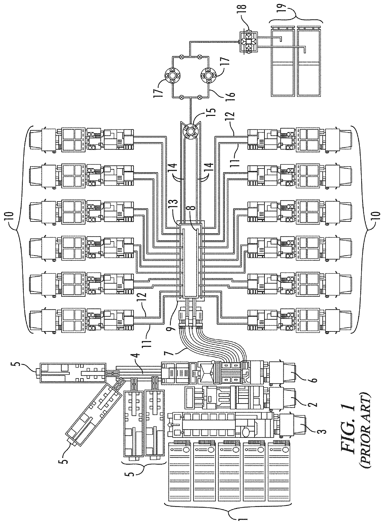
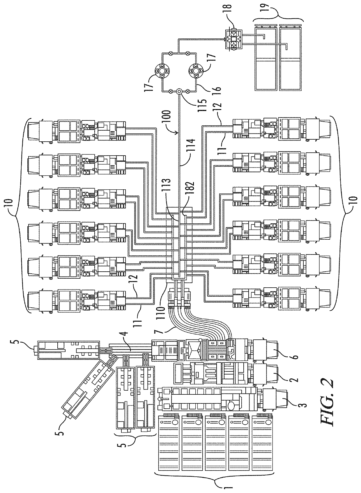
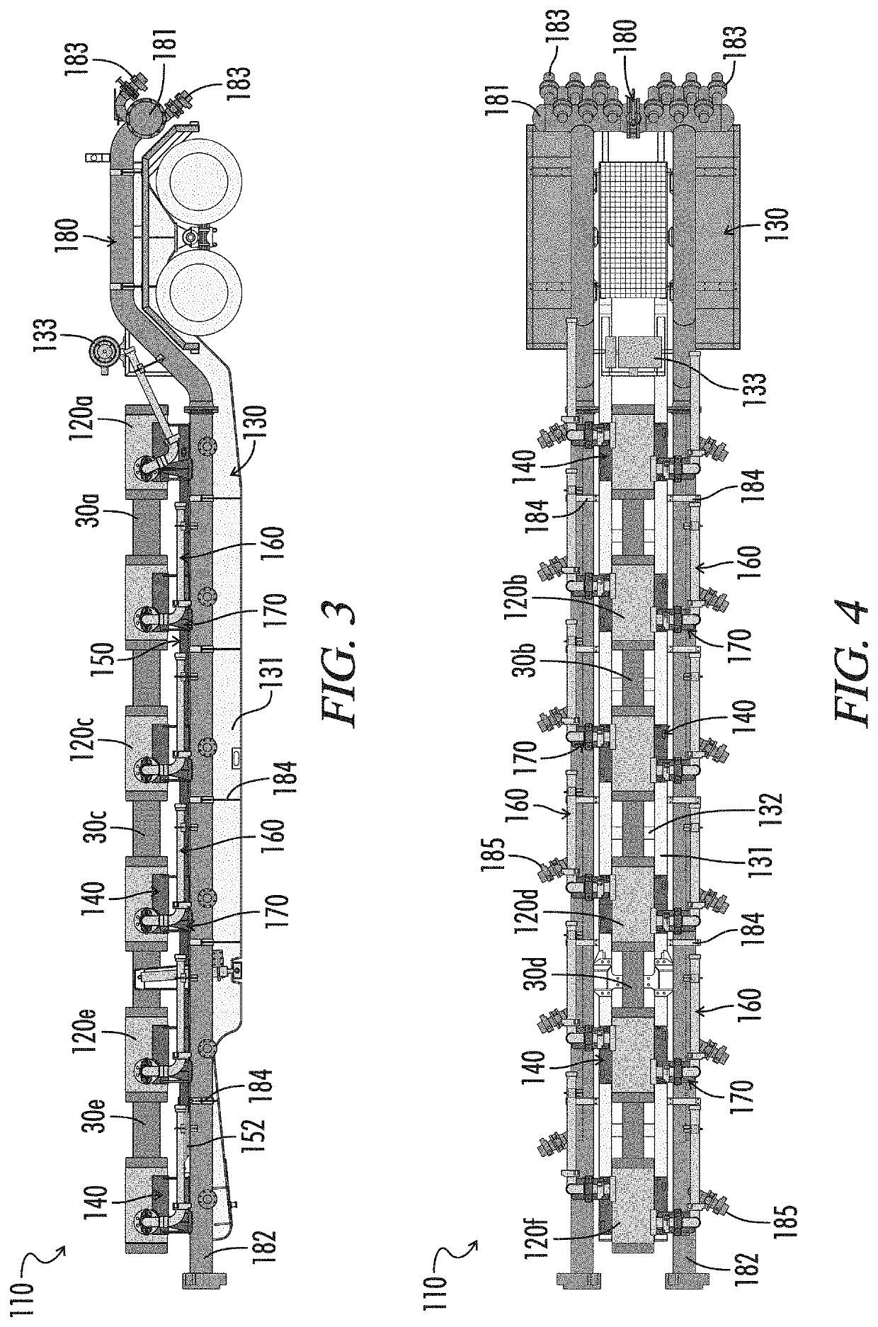
[0153]The invention, in various aspects and embodiments, is directed generally to fluid transportation systems and flow lines used in those systems, and especially to frac trailers, frac manifolds, flow lines, and flowline components that are used to convey abrasive, corrosive fluids under high pressure. Various specific embodiments will be described below. For the sake of conciseness, however, all features of an actual implementation may not be described or illustrated. In developing any actual implementation, as in any engineering or design project, numerous implementation-specific decisions must be made to achieve a developer's specific goals. Decisions usually will be made consistent within system-related and business-related constraints. Specific goals may vary from one implementation to another. Development efforts might be complex and time consuming and may involve many aspects of design, fabrication, and manufacture. Nevertheless, it should be appreciated that such developme...


PUM


Abstract

Flowline junction fittings are assembled to missiles of frac manifolds. The fittings have a body with a primary bore, at least four secondary bores, and a tertiary bore. The bores extend from union faces adapted for connection to flowline components by a flange union. The tertiary bore intersects with the primary bore at an angle of approximately 90°. Goat head fittings are assembled to well heads. The goat heads have a body with a primary bore and at least four secondary bores. The bores extend from union faces adapted for connection to flowline components by a flange union. The intersections between the secondary bores and the primary bore have an interior angle of substantially less than 90°.

Description

FIELD OF THE INVENTION[0001]The present invention relates generally to fluid transportation systems and flow lines used in those systems, and especially to frac manifolds, flow lines, and flowline components used to convey abrasive, corrosive fluids under high pressure as are common, for example, in the oil and gas industry.BACKGROUND OF THE INVENTION[0002]Hydrocarbons, such as oil and gas, may be recovered from various types of subsurface geological formations. The formations typically consist of a porous layer, such as limestone and sands, overlaid by a nonporous layer. Hydrocarbons cannot rise through the nonporous layer. Thus, the porous layer forms a reservoir, that is, a volume in which hydrocarbons accumulate. A well is drilled through the earth until the hydrocarbon bearing formation is reached. Hydrocarbons then can flow from the porous formation into the well.[0003]In what is perhaps the most basic form of rotary drilling methods, a drill bit is attached to a series of pip...

Claims


Application Information

Patent Timeline
Patent Type & Authority Patents(United States)
IPC IPC(8): E21B43/26E21B17/04F16L41/02F16L23/02F16L23/032F16L41/03F16L41/00F16L23/12F16L41/04F16L41/08
CPCF16L23/02F16L41/008F16L41/04F16L23/032F16L41/00F16L23/12E21B17/04E21B43/26F16L41/03F16L41/02F16L41/088E21B43/2607F16L3/1091F16L41/021F16L41/023F16L41/086F16L55/11
Inventor HILL, LARRY MITCHELSTROEBEL, WILLIAM BRENTDONALDSON, SCOTT TAYLORCOLLEY, III, E. LEE
Owner KHOLLE MAGNOLIA 2015 LLC
Why Eureka
Try Eureka