Membrane electrode assembly

a technology of membrane electrodes and components, applied in the direction of fuel cell details, cell components, electrochemical generators, etc., can solve the problems of difficult to efficiently discharge the produced water, and flooding may occur

Active Publication Date: 2020-07-07
HONDA MOTOR CO LTD
View PDF5 Cites 1 Cited by
  • Summary
  • Abstract
  • Description
  • Claims
  • Application Information

AI Technical Summary

Benefits of technology

[0010]A main object of the present invention is to provide a membrane electrode assembly in which it is possible to achieve a suitable balance between the water retention capability and the water drainage capability in each electrode even in conditions of low temperature and high humidity.
[0011]Another object of the present invention is to provide a membrane electrode assembly which makes it possible to obtain a fuel cell exhibiting high terminal voltage.
[0020]The cathode may further include a hydrophilic layer interposed between the second porous layer and the second electrode catalyst layer. The hydrophilic layer closes minute cracks of the second porous layer, and suppresses deformation of the electrolyte membrane. Further, the hydrophilic property of the hydrophilic layer provides the water retention capability.
[0022]Further, preferably, the first porous layer and the second porous layer contain vapor-grown carbon fiber. The vapor-grown carbon fiber has sufficient electron conductivity and pore forming capability even though the vapor-grown carbon fiber has a low density. Therefore, it is possible to achieve reduction in the weight of the membrane electrode assembly.
[0024]In the structure, under both the environment of low temperature and high humidity and the environment of high temperature and high humidity, it is possible to achieve a suitable balance between the water drainage capability and the water retention capability. Therefore, in any of the environment of low temperature and high humidity and the environment of high temperature and high humidity, it is possible to provide a fuel cell having a sufficient power generation performance.

Problems solved by technology

At the cathode, when the operating temperature of the fuel cell stack is low, and the humidity of the oxygen-containing gas is high, it is difficult to discharge the produced water efficiently.
In this case, so called flooding may occur.

Method used


Image

  • Membrane electrode assembly
  • Membrane electrode assembly
  • Membrane electrode assembly

Examples


embodiment example 1

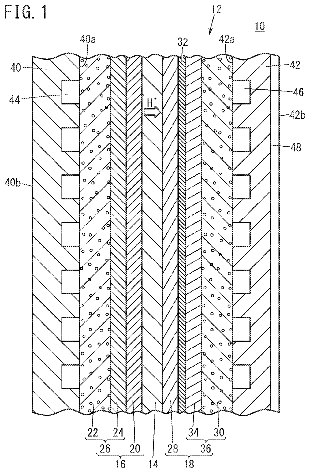
[0067]A carbon paper having a bulk density of 0.34 g / m2 and a thickness of 150 μm was impregnated with a dispersion liquid of a tetrafluoroethylene-hexafluoropropylene copolymer (FEP), “FEP120JRB” (trade name) available from Du Pont-Mitsui Fluorochemicals Co., Ltd., and the resultant paper was dried at 120° C. for 30 minutes. Further, the paper was heat-treated at 380° C. to produce a first gas diffusion layer 22.

[0068]In the meanwhile, 20 g of a vapor-grown carbon fiber VGCF available from Showa Denko K.K., 5 g of FEP120JRB, and 200 g of ethylene glycol were stirred and mixed using a ball mill to prepare a paste for forming a first porous layer. Further, the first porous layer paste was applied by a coater onto the first gas diffusion layer 22, and heat-treated at 380° C. for 30 minutes, to thereby form the first porous layer 24. That is, the first stack body 26 comprising the first gas diffusion layer 22 and the first porous layer 24 was obtained. The dry weight per unit area of t...

embodiment examples 2 to 4

[0078]The unit cell 10 was produced in the same manner as in the case of Embodiment Example 1 except that the dry weight per unit area of the second porous layer 34 was 1.4 mg / cm2 in Embodiment Example 2, 1.6 mg / cm2 in Embodiment Example 3, and 1.9 mg / cm2 in Embodiment Example 4.


PUM

PropertyMeasurementUnit
pore diameteraaaaaaaaaa

Abstract

In pore diameter distribution curves of a first stack body formed by stacking a first gas diffusion layer and a first porous layer of an anode, and of a second stack body formed by stacking a second gas diffusion layer and a second porous layer of a cathode, on a region where a pore diameter is smaller than a reference pore diameter at which a pore volume is maximum, both the curves coincide with each other for the most part. On a region where the pore diameter is equal to or larger than the reference pore diameter, the distribution curve of the second stack body lies above that of the first stack body. A pore volume ratio which is a ratio of the total pore volume of the second stack body to the total pore volume of the first stack body is in the range of 1.10 to 1.60.

Description

CROSS-REFERENCE TO RELATED APPLICATION[0001]This application is based upon and claims the benefit of priority from Japanese Patent Application No. 2017-052330 filed on Mar. 17, 2017, the contents of which are incorporated herein by reference.BACKGROUND OF THE INVENTIONField of the Invention[0002]The present invention relates to a membrane electrode assembly including an anode, a cathode, and a solid polymer electrolyte membrane interposed between the anode and the cathode.Description of the Related Art[0003]A membrane electrode assembly of a solid polymer electrolyte fuel cell includes an anode, a cathode, and an electrolyte membrane interposed between the anode and the cathode. The electrolyte membrane is made of sulfone group-containing resin. The anode faces one surface of the electrolyte membrane, and the cathode faces the other surface of the electrolyte membrane. Each of the anode and the cathode chiefly contains metal catalyst such as platinum, platinum alloy, etc., and inclu...

Claims


Application Information

Patent Timeline
Patent Type & Authority Patents(United States)
IPC IPC(8): H01M8/10H01M8/04H01M8/02H01M4/92H01M4/86H01M8/1004H01M8/0239H01M8/04119H01M8/1039H01M8/0234H01M8/1018
CPCH01M4/8626H01M8/04171H01M8/1039H01M8/0239H01M8/0234H01M4/926H01M8/1004H01M2300/0082H01M2004/8684H01M2008/1095H01M2004/8689Y02E60/50
Inventor ASANO, YOICHIYAMAWAKI, TAKUMA
Owner HONDA MOTOR CO LTD
Why Eureka
Try Eureka