
Rare earth solution image capture device and method

a technology of image capture and solution, applied in image enhancement, image data processing, instruments, etc., can solve the problems of inability to accurately reflect a real situation in real time, large waste of manpower, material resources and time, and difficulty in real-time control, so as to reduce labor intensity and improve efficiency.

Active Publication Date: 2020-07-14
EAST CHINA JIAOTONG UNIVERSITY
View PDF1 Cites 4 Cited by
  • Summary
  • Abstract
  • Description
  • Claims
  • Application Information

AI Technical Summary

Benefits of technology

The patent text describes a rare earth solution image capture device and method that can automatically and continuously sample and detect rare earth solutions. The device includes a mixer-settler, support platform, camera obscura, solution collection vessel, color camera, light source, computer, programmable logic controller, motor driver, peristaltic pump, and conduit pipe. The device can capture, transmit, and process images quickly and efficiently. Additionally, the device can extract color feature information from rare earth solutions, providing useful data for predictive modeling.

Problems solved by technology

As a result, there is obvious hysteresis of control strategy adjustment and it is difficult to perform control in real time.
If component content of elements of an export product is not within a production requirement, the elements of the export product need to be extracted again, leading to a great waste of manpower, material resources, and time.
However, a rare earth solvent extraction is a continuous process, and consequently the off-line detection method cannot accurately reflect a real situation in real time.
This method requires an operator to perform an actual operation at an extraction site, and therefore there is a specific delay.
As a result, there is a problem of a detection delay in the spectrophotometric method.
This ray analysis method can only be used for single detection, and therefore cannot perform continuous detection.
Thus, the existing detection methods have a problem of not being able to perform continuous detection in real time.

Method used


Image

  • Rare earth solution image capture device and method
  • Rare earth solution image capture device and method
  • Rare earth solution image capture device and method

Examples


embodiment 1

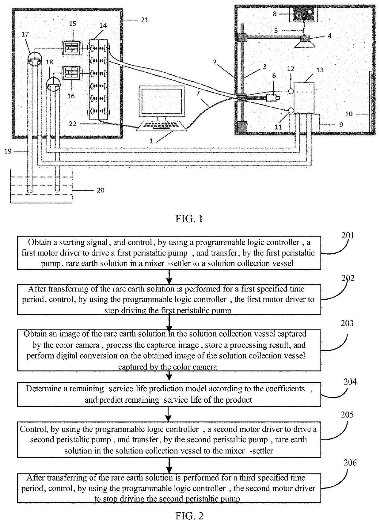
[0025]This embodiment provides a rare earth solution image capture device. FIG. 1 is a structural diagram of the rare earth solution image capture device according to Embodiment 1 of the disclosure. Referring to FIG. 1, the rare earth solution image capture device includes a mixer-settler 20, a support platform 9, a camera obscura 2, a solution collection vessel 13, a color camera 6, a light source, a computer 1, a programmable logic controller 14, a motor driver, a peristaltic pump, and a conduit pipe 19.

[0026]The mixer-settler 20 and the solution collection vessel 13 may be used to accommodate rare earth solution. The support platform 9, the solution collection vessel 13, the color camera 6, and the light source are all disposed in the camera obscura 2. The camera obscura 2 may be used to isolate an external light source. The solution collection vessel 13 is disposed on the support platform 9. The color camera 6 directly faces the solution collection vessel 13. The color camera 6 ...

embodiment 2

[0034]This embodiment provides a rare earth solution image capture method, implemented by the rare earth solution image capture device in Embodiment 1.

[0035]FIG. 2 is a flowchart of a rare earth solution image capture method according to Embodiment 2 of the present invention. Referring to FIG. 2, the rare earth solution image capture method includes the following steps:

[0036]Step 201. Obtain a starting signal, and control, by using a programmable logic controller, a first motor driver to drive a first peristaltic pump, and transfer, by the first peristaltic pump, rare earth solution in a mixer-settler to a solution collection vessel.

[0037]Step 202. After transferring of the rare earth solution is performed for a first specified time period, control, by using the programmable logic controller, the first motor driver to stop driving the first peristaltic pump.

[0038]Step 203. After standing is performed for a second specified time period, regulate a position and luminance of a light so...

embodiment 3

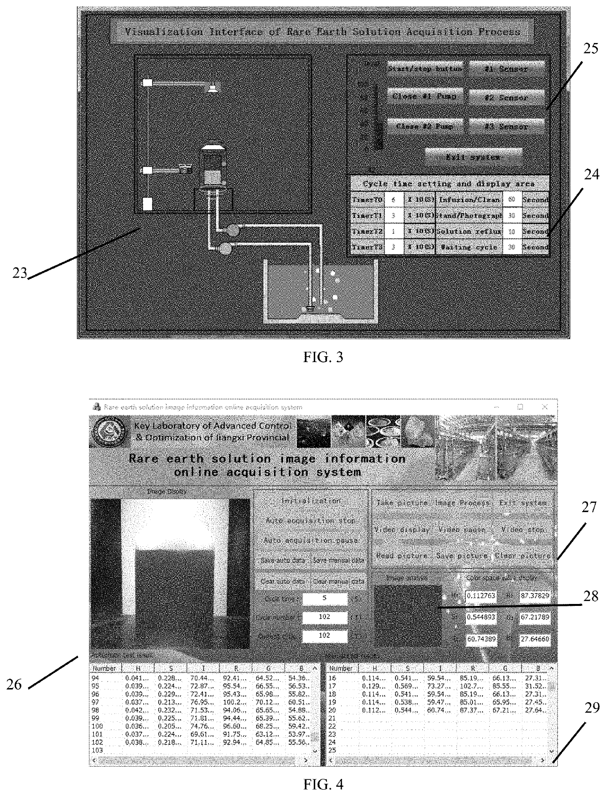
[0042]This embodiment provides a rare earth solution image capture device. The rare earth solution image capture device includes a rare earth extraction solution collection and image acquisition hardware platform and upper computer control software.

[0043]The rare earth extraction solution collection and image acquisition hardware platform includes a computer, a camera obscura, a movable rail bracket, a light source, a USB data cable, a color camera, a 1394 data cable, a light source regulator, a support platform, a white balance grey chip, a liquid level sensor, a solution collection vessel, a programmable logic controller (Programmable Logic Controller, PLC), a motor driver, a peristaltic pump, and a conduit pipe, a network cable, and several wires.

[0044]The mixer-settler and the solution collection vessel may be used to accommodate rare earth solution.

[0045]The support platform, the solution collection vessel, the color camera, and the light source are all disposed in the camera o...


PUM

PropertyMeasurementUnit
Timeaaaaaaaaaa
Coloraaaaaaaaaa
Ratioaaaaaaaaaa

Abstract

A method and device relate to rare earth solution image capturing, and further relate to the field of rare earth hydrometallurgical process detection technologies. According to an embodiment, a rare earth solution image capture device includes a mixer-settler, a support platform, a camera obscura, a solution collection vessel, a color camera, a light source, a computer, a programmable logic controller, a motor driver, a peristaltic pump, and a conduit pipe. According to another embodiment, the rare earth solution image capture device performs automatic sampling by using the programmable logic controller and may perform detection at any time. An image captured by the color camera may be transmitted to the computer in real time without manual intervention.

Description

CROSS REFERENCE TO RELATED APPLICATIONS[0001]This application claims priority to Chinese application number 20191012812-8.9 filed on Feb. 21, 2019, the disclosure of which is incorporated by reference herein in its entirety.FIELD OF THE DISCLOSURE[0002]The disclosure relates generally to the field of rare earth hydrometallurgical process detection technologies. More specifically, the disclosure relates to the field of a rare earth solution image capture device and method.BACKGROUND[0003]Rare earth elements, known as the “vitamin” of industry, are key materials used in many electronic products and weapon systems. Because of numerous components of a rare earth material and very similar properties of rare earth elements, cascade extraction is usually used in the industrial production of rare earth to complete separation of elements in the rare earth material. In order to obtain single high-purity rare earth elements, a mixer-settler used in rare earth extraction and separation sometime...

Claims


Application Information

Patent Timeline
IPC IPC(8): G01J3/42G06T7/194C22B59/00G01N21/84G01N21/27G06T7/90
CPCG06T7/90G01N21/27G01N21/84C22B59/00G06T7/194G06T2207/10024G06T2207/20032G06T7/11G06T7/136G06T2207/30108
Inventor LU, RONGXIURAO, YUNCHUNYANG, HUIZHU, JIANYONGYANG, GANG
Owner EAST CHINA JIAOTONG UNIVERSITY
Learn More