Air-cooled heat exchanger and thermal arrangement for stacked electronics
a heat exchanger and stacking technology, applied in the field of packaging and improving the cooling of electronic components, to achieve the effect of high power density electronics and similar level of performan
- Summary
- Abstract
- Description
- Claims
- Application Information
AI Technical Summary
Benefits of technology
Problems solved by technology
Method used
Image
Examples
first embodiment
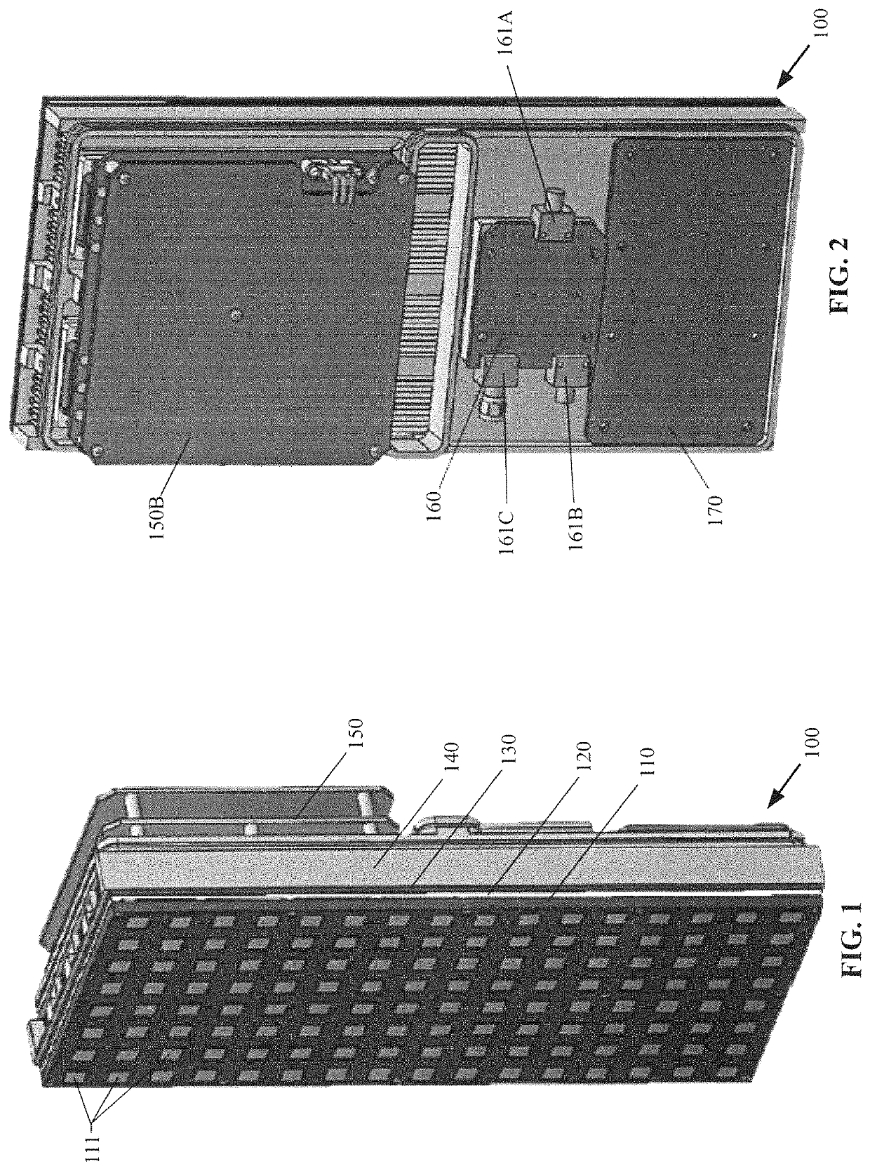
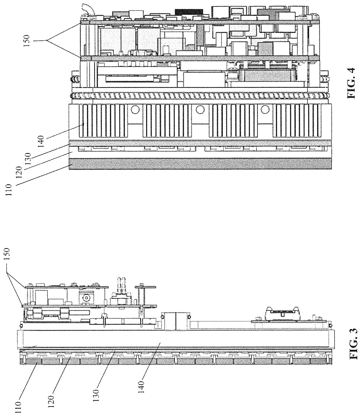
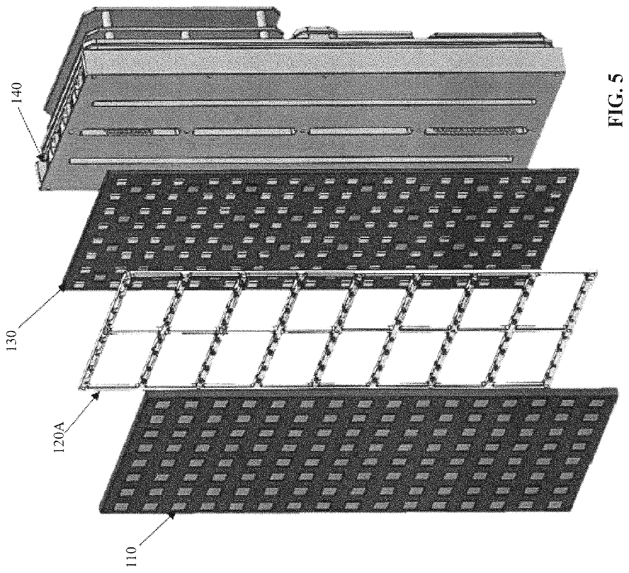
[0124]FIGS. 1-4 illustrate perspective, side, and top views of a stacked electronics package 100, and FIGS. 6A-8 illustrate exploded views of the component parts of that stacked electronics package. As seen therein, the stacked electronics package 100 may include a passive radiator circuit card assembly 110, a tile frame 120, an active tile circuit card assembly 130, a heat exchanger 140, a tile power converter 150, a tile combiner 160, and a tile controller circuit card assembly 170. Each circuit card assembly (CCA) herein may include a printed circuit board populated with electronic components that may include millimeter monolithic integrated circuits (MIMICs).
[0125]The passive radiator circuit card assembly 110 may be formed, in one embodiment, of a plurality of radiating elements 111 (e.g., patch radiators plugins) that may be imprinted into the inner board layers. Each radiator plug-in may be formed of a printed wiring board (PWB) stack-up of various RF materials (e.g., RO3003™...
second embodiment
[0141]FIG. 37 is a colored thermal plot of a heat exchanger formed to be different than the heat exchanger of FIGS. 16-18 and FIGS. 20A, 21A. 22A, and 22B, as it has air intake at only one end, and air exhaust at the opposite end;
[0142]The heat exchanger 140 with a double inlet having an inlet at each of the opposite ends and the common central exhaust plenum serves to create a very uniform temperature gradient across all components within the electronic system.
[0143]Both FIG. 37 and FIG. 40 represent steady state conditions, but there is a difference in the maximum temperature reached; the single intake heat exchanger in FIG. 37 reaches a maximum temperature of 92.77° C., while the dual intake heat exchanger of FIG. 40 reaches a maximum temperature of 84.33° C., which temperature may result from a mass flow rate of about 3.2 lbs / min.
[0144]FIGS. 33-36 illustrate a multi-member array of stacked electronics packages, each formed in accordance with the embodiment of FIG. 1;
[0145]FIGS. ...
PUM
 Abstract
Description
Claims
Application Information
 - R&D
- Intellectual Property
- Life Sciences
- Materials
- Tech Scout
- Unparalleled Data Quality
- Higher Quality Content
- 60% Fewer Hallucinations
Browse by: Latest US Patents, China's latest patents, Technical Efficacy Thesaurus, Application Domain, Technology Topic, Popular Technical Reports.
© 2025 PatSnap. All rights reserved.Legal|Privacy policy|Modern Slavery Act Transparency Statement|Sitemap|About US| Contact US: help@patsnap.com


