
Urea process with high-temperature stripping

a high-temperature stripping and urea technology, applied in the chemical industry, distillation separation, organic compound preparation, etc., can solve the problems of limited efficiency of the conventional stripping process, achieve higher conversion of reactors, reduce energy consumption of strippers, and improve the effect of energy efficiency

Active Publication Date: 2020-09-22
CASALE SA
View PDF8 Cites 1 Cited by
  • Summary
  • Abstract
  • Description
  • Claims
  • Application Information

AI Technical Summary

Benefits of technology

[0025]Achieving a higher conversion of carbon dioxide to urea in the high pressure loop, that is a less amount of unconverted carbamate in the effluent, is a great advantage of the invention and reduces the size and cost of a subsequent low-pressure recovery section and the amount of water which is inevitably recycled to the reactor. In some embodiments of the invention, the effluent of the high-pressure stripper is sent directly to a concentration and finishing section, i.e. without any step of carbamate decomposition at a pressure lower than synthesis pressure.
[0026]The invention also achieves higher energy efficiency. By reintroducing less water into the reactor, the invention obtains a higher conversion of reactor (i.e. 70% against 60-63% of common reactors) and, consequently, a lower energy consumption of the stripper and globally of the plant if compared to the prior art. Also, the condenser is able to export a greater amount of energy, preferably in the form of steam. The additional steam can be used, for example, to power a steam turbine driver of the carbon dioxide compressor.
[0027]Further objects of the invention are stated in the attached claims.
[0028]The advantages will emerge even more clearly with the aid of the description below, relating to a preferred embodiment.

Problems solved by technology

The applicant has found that one reason behind the limited efficiency of the conventional stripping process is that the decomposition temperature of the residual ammonium carbamate in the reactor effluent is above 200° C. at the typical pressure of urea synthesis.

Method used

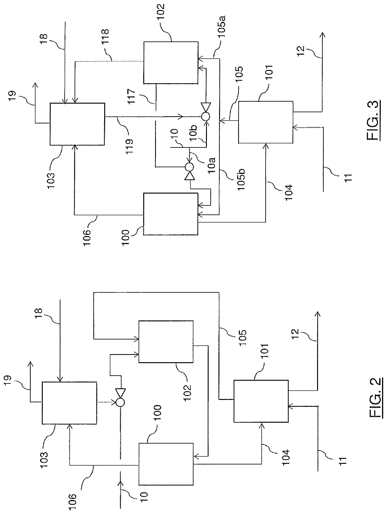

Image

  • Urea process with high-temperature stripping
  • Urea process with high-temperature stripping
  • Urea process with high-temperature stripping

Examples


Embodiment Construction

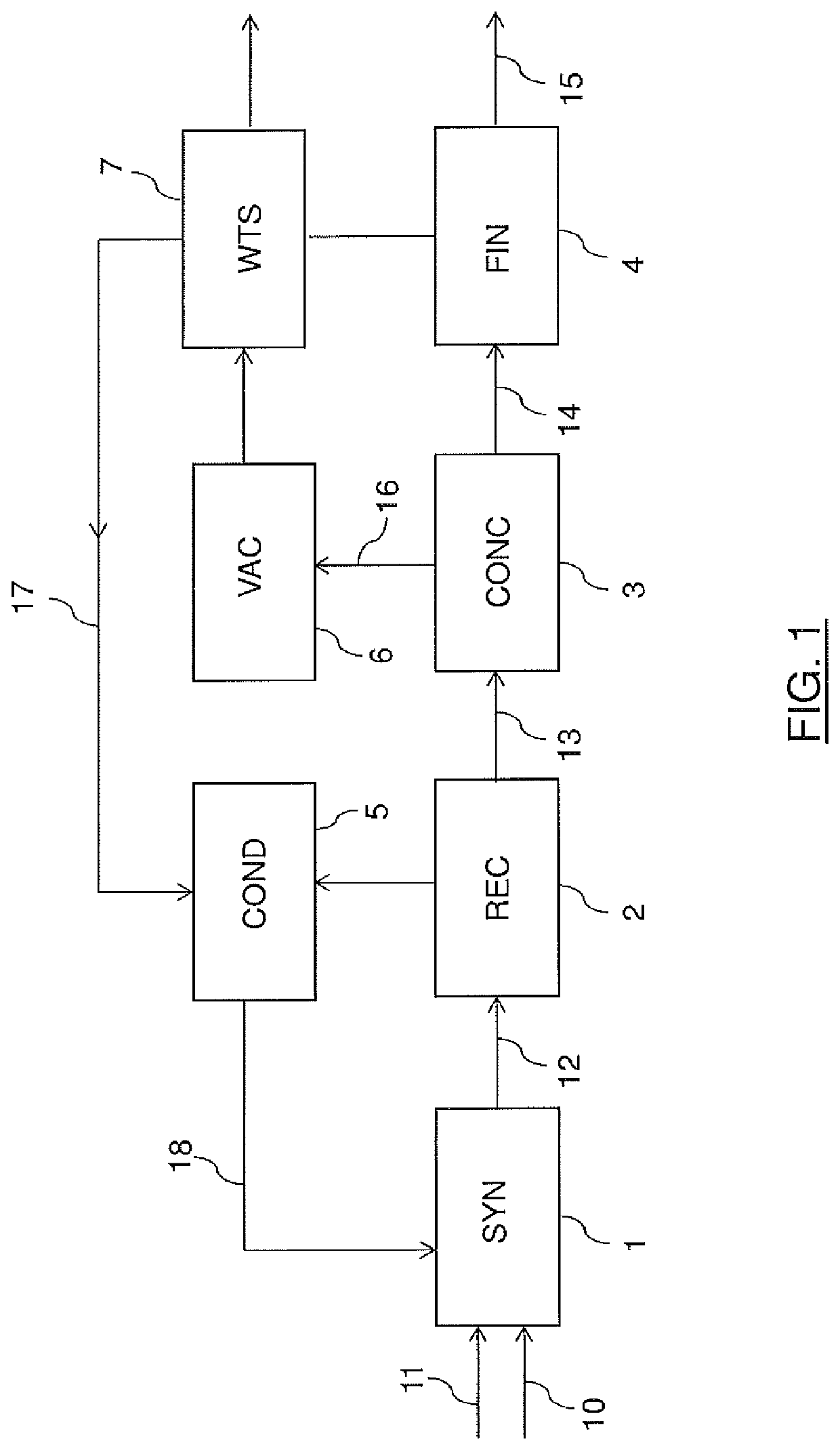
[0038]FIG. 1 illustrates a block scheme of a urea plant according to a first embodiment of the invention.

[0039]The urea plant comprises basically: a high-pressure synthesis section (SYN) 1, a recovery section (REC) 2, a vacuum concentration section (CONC) 3, a finishing section (FIN) 4, a condensation and recycle section (COND) 5, a vacuum condensation unit (VAC) 6 and a waste water treatment section (WTS) 7.

[0040]Ammonia feed 10 and carbon dioxide feed 11 are reacted in the synthesis section 1 to produce an aqueous solution 12 of urea; said solution 12 is further treated in the recovery section 2 which comprises at least one decomposition unit where unconverted carbamate contained in the solution 12 is decomposed to ammonia and carbon dioxide.

[0041]The output of said section 2 is an aqueous solution 13 which is sent to the vacuum concentration unit 3 where water is removed until a desired concentration is reached, suitable for finishing in the subsequent section 4.

[0042]The stream ...


PUM

PropertyMeasurementUnit
temperatureaaaaaaaaaa
pressureaaaaaaaaaa

Abstract

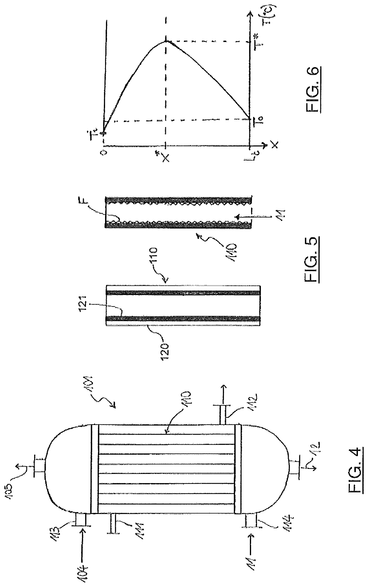
A shell-and-tube stripper for carbamate decomposition and ammonia recovery from a urea solution comprising a bundle of heated tubes, said tubes being fed with said urea solution and carbon dioxide as stripping medium, the urea solutions forming a liquid falling film on the internal surface of the tubes and the carbon dioxide forming a counter-current gaseous flow; said tubes comprise an external layer made of super austenitic or super duplex stainless steel and an internal layer made of zirconium, said internal layer reaching temperatures higher than 220° C.

Description

[0001]This application is a national phase of PCT / EP2016 / 080443, filed Dec. 9, 2016, and claims priority to EP 15199482.9, filed Dec. 11, 2015, the entire contents of both of which are hereby incorporated by reference.Field of the Invention[0002]The invention relates to the field of urea production. The invention relates in particular to high-temperature stripping in a process for the urea production.Prior Art[0003]Urea is synthesized by reacting ammonia and carbon dioxide. A discussion of the various processes and related plants for the urea production can be found in literature, e.g. Ullmann's Encyclopedia of Industrial Chemistry, Wiley-VCH Verlag.[0004]The synthesis of urea involves a fast and highly exothermic step of formation of ammonium carbamate, and a slightly endothermic step of conversion of ammonium carbamate into urea and water. The reaction is carried out in a urea synthesis reactor, which is generally operated at 130-250 bar and 180-200° C.[0005]Due to thermodynamic l...

Claims


Application Information

Patent Timeline
Patent Type & Authority Patents(United States)
IPC IPC(8): C07C273/04B01D3/04C07C273/16B01D1/06B01D3/00
CPCB01D1/065B01D3/04C07C273/16B01D3/009C07C273/04Y02P20/10B01D1/06
Inventor RUGNONE, LUCA
Owner CASALE SA
Learn More