Supply device for a motor vehicle

a technology for motor vehicles and supply devices, applied in battery/fuel cell control arrangements, propulsion by batteries/cells, transportation and packaging, etc., can solve the problems of increasing efficiency and operating in a range with lower efficiency, and achieve good current supply, good efficiency, and advantageous range

Active Publication Date: 2020-10-13
DR ING H C F PORSCHE AG
View PDF15 Cites 2 Cited by
  • Summary
  • Abstract
  • Description
  • Claims
  • Application Information

AI Technical Summary

Benefits of technology

[0008]By switching back and forth between the first state and the second state, it is possible to operate the DC / DC converter in an operating range with higher efficiency, and the losses can thus be reduced. This results in an increase in efficiency vis-à-vis a DC / DC converter which always actively carries out a conversion and in so doing operates in an operating range with lower efficiency.
[0012]In accordance with one preferred embodiment, the control device is configured, depending on an instantaneously required electrical power at the second outputs, to determine a suitable ratio of the time duration of the first state and the time duration of the second state and to drive the DC / DC converter accordingly. This adaptation of the time duration makes it possible to operate the DC / DC converter in an advantageous range.
[0013]In accordance with one preferred embodiment, the ratio of the time duration of the first state and the time duration of the second state is smaller in the case of a first instantaneously required electrical power than in the case of a second instantaneously required electrical power, which is higher than the first instantaneously required electrical power. This makes possible, in the case of high powers or consumptions, a good current supply and smaller interruptions by the second state.
[0014]In accordance with one preferred embodiment, the control device is configured, depending on an instantaneously required electrical power at the second outputs, to determine a suitable period duration for a period from first state and second state and to drive the DC / DC converter accordingly. This makes it possible to operate the DC / DC converter in a particularly advantageous range with good efficiency.
[0015]In accordance with one preferred embodiment, the period duration for a period from first state and second state is smaller in the case of a first instantaneously required electrical power than in the case of a second instantaneously required electrical power, which is higher than the first instantaneously required electrical power. What can be achieved as a result is that in the case of the lower first instantaneously required electrical power on the part of the DC / DC converter the pulse duration does not become excessively small.
[0019]In accordance with one preferred embodiment, the instantaneously required electrical power is determined both depending on a measurement of a current from the second energy storage to the load and depending on a measurement of the voltage at the second energy storage or the state of charge of the second energy storage. By way of example, the higher value or the average value can be used. This results in a faster adaptation of the power. Taking account of the state of charge of the second energy storage and the current to the load is advantageous since a large load and hence a high current to the load can occur even given a sufficient state of charge. Provision of the required power by the DC / DC converter results in a smaller discharge of the second energy storage and conserves the latter.

Problems solved by technology

This results in an increase in efficiency vis-à-vis a DC / DC converter which always actively carries out a conversion and in so doing operates in an operating range with lower efficiency.

Method used


Image

  • Supply device for a motor vehicle
  • Supply device for a motor vehicle

Examples


Embodiment Construction

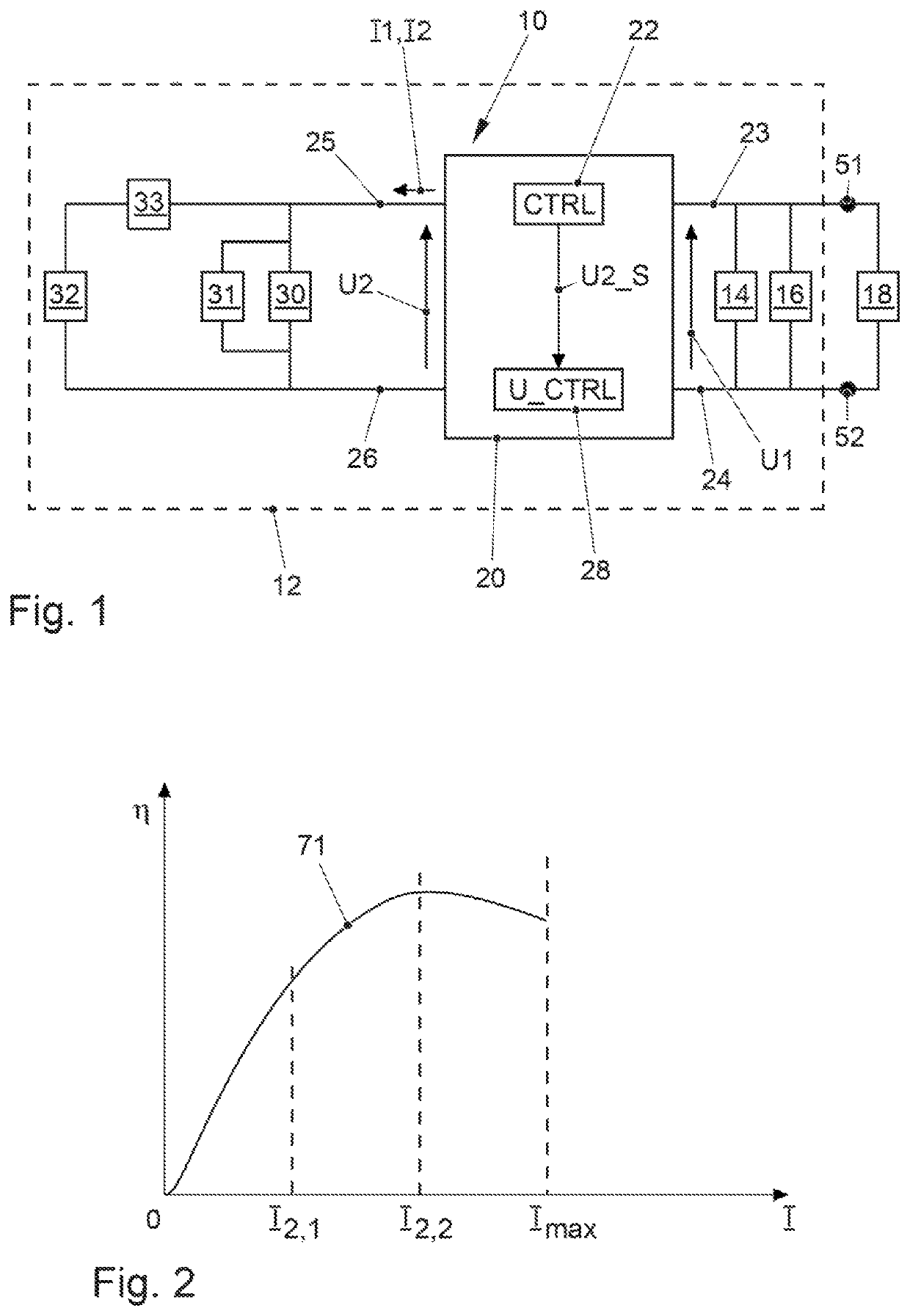
[0028]FIG. 1 shows a motor vehicle 12 in a schematic illustration. The motor vehicle 12 has an energy storage 14 and a load 16 which is connectable to the energy storage 14, wherein the energy storage 14 operates with a first voltage U1, preferably a high voltage of e.g. 200 volts, 400 volts or 800 volts. The motor vehicle 12 has a further energy storage 30 and a load 32 which is connectable to said energy storage 30, wherein the energy storage 30 operates with second voltage U2, which is preferably lower than the first voltage U1. The second terminals 25, 26 are preferably provided for connecting an on-board electrical system. The energy storage 30 preferably has a high efficiency and a high cycle endurance. The second voltage U2 is e.g. 12 volts, 24 volts or 48 volts. A supply device 10 has a control device 22 and a DC / DC converter 20. The DC / DC converter 20 is provided or interconnected between the energy storage 14 and the energy storage 30. The DC / DC converter 20 has first term...


PUM


Abstract

A supply device for a motor vehicle has a DC / DC converter and a control device for the DC / DC converter. The DC / DC converter has first terminals and second terminals, which first terminals are configured for electrical connection to a first energy storage or a first energy source and which second terminals are configured for electrical connection to a second energy storage or a load. The DC / DC converter is configured, in a first state to enable a conversion of a first DC voltage at the first terminals into a lower second DC voltage at the second terminals and, in a second state, to carry out no conversion of a first DC voltage at the first terminals into a lower second DC voltage at the second terminals. The control device enables an energy supply at the second terminals by repeatedly changing the DC / DC converter between the first state and the second state.

Description

CROSS-REFERENCE TO RELATED APPLICATION[0001]This application claims priority to German Patent Application No. DE 10 2018 100 988.7, filed Jan. 17, 2018, which is incorporated by reference herein in its entirety.FIELD OF THE INVENTION[0002]The invention relates to a supply device for a motor vehicle.BACKGROUND OF THE INVENTION[0003]DE 10 2013 219 293 A1, which is incorporated by reference herein, discloses a vehicle having a high-voltage on-board electrical system, a low-voltage on-board electrical system and having a DC chopper between these on-board electrical systems. The high-voltage electrical system has a high-voltage energy storage element and the low-voltage electrical system has a low-voltage energy storage element. In a stationary phase, the DC chopper is used to load the low-voltage energy storage element by supplementarily connecting consumers from the high-voltage on-board electrical system and then to evaluate the response of the low-voltage energy storage.[0004]US 2001...

Claims


Application Information

Patent Timeline
Patent Type & Authority Patents(United States)
IPC IPC(8): B60L53/10H02J7/34H02J7/00B60R16/03B60L50/60B60L58/18
CPCH02J7/342B60R16/03B60L53/11H02J7/0049H02J7/00H02J7/0068B60L58/18B60L50/60H02J2207/20B60L2210/10H02M3/00H02J2310/46Y02T10/72Y02T10/70Y02T90/14Y02T10/7072
Inventor VIENKEN, CHRISTIANLABONTE, DOMINIQUESTEINHORST, ULRICHTHELE, MARCSCHUMACHER, MICHAEL
Owner DR ING H C F PORSCHE AG
Why Eureka
Try Eureka