Piston for a cylinder for an internal combustion engine

a technology of internal combustion engine and piston top, which is applied in the direction of machines/engines, mechanical devices, coatings, etc., can solve the problems of increased pressure and temperature of the piston top during combustion, increased demands, and high demands on the piston top, and achieve satisfactory bonding and bonding of the bond material

Active Publication Date: 2020-10-13
VOLVO TRUCK CORP
View PDF22 Cites 1 Cited by
  • Summary
  • Abstract
  • Description
  • Claims
  • Application Information

AI Technical Summary

Benefits of technology

[0008]The thermal barrier coating has commonly been provided on the whole piston surface in order to insulate the underlying piston material from the direct heat influence and to reduce the heat build-up. When instead providing the thermal barrier coating on a plurality of circumferentially spaced surface parts of the piston bowl surface the heat load is reduced underneath the coated surface parts, whereas the uncoated surface parts are open for heat reception. In comparison to the commonly designed piston, the piston according to this disclosure is assimilating more heat energy such that surrounding parts of the combustion chamber is exposed to less heat, and at the same time the heat is more evenly distributed within the piston. Underneath the coated surface parts the maximum temperature is reduced in comparison to the general un-coated design, whereas the maximum temperature at the uncoated surface parts may be somewhat increased. The heat energy is hence more evenly distributed within the piston and the maximum temperature at any single point is reduced such that the risk for material degradation is reduced and the risk for coke build-up underneath the piston crown is also reduced. The thermal expansion of the piston material and the coating may be different causing high stresses in the coating with the risk of coating crack and / or delamination from the piston material. Having a plurality of coated parts of the piston will allow larger thermal expansion of the piston material with less stress build-up in the coating. Thereby the durability and expected longevity of the piston is consequently increased.
[0044]According to an embodiment the openings of the second masking device is smaller than the openings of the third masking device. This is a simple manner to achieve a satisfactory bonding of the bond material to the piston bowl surface.

Problems solved by technology

Developments relating to for example the combustion process and to the design of the engine itself have led to an increase in resulting pressures and temperatures within the cylinders during the combustion.
This in turn puts increased demands on such issues like the materials of which the engine is made, and in particular on the parts which are in direct contact with the combustion process such as the cylinder head, cylinder and piston.
The piston top is subjected to high demands.
High temperatures in the piston material is also a cause of building of coke on the areas of the piston in contact with oil.
A problem arising from the application of an insulating coating on the piston surface is that although the piston itself is protected from the high demands, the heat is instead conveyed to and absorbed by the surrounding parts of the combustion chamber, where the heat is built up in an uncontrolled manner and similar problems as for the piston may arise.
It is still a problem to handle the build-up of heat in parts within and surrounding the combustion chamber of an internal combustion engine.
The thermal expansion of the piston material and the coating may be different causing high stresses in the coating with the risk of coating crack and / or delamination from the piston material.
Such materials are having a low thermal conductivity.

Method used


Image

  • Piston for a cylinder for an internal combustion engine
  • Piston for a cylinder for an internal combustion engine
  • Piston for a cylinder for an internal combustion engine

Examples


Embodiment Construction

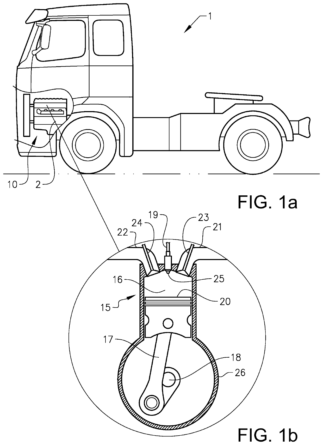
[0065]With reference to FIG. 1a a heavy duty truck 1 is disclosed for which an internal combustion engine system 10 of a kind disclosed in the present disclosure is advantageous. However, the internal combustion engine system 10 may well be implemented also in other types of vehicles, such as in busses, in light-weight trucks, passenger cars, marine applications etc. The internal combustion engine system 10 comprises a compression ignition internal combustion engine 2. The internal combustion engine 2 may be e.g. a diesel engine, which as such may be running on several different types of fuel, such as diesel or dimethyl ether, DME. Other fuel types are well suited, as well as hybrid systems. The internal combustion engine system 10 is provided with at least one, and preferably six to eight cylinders 15, each one having a piston 20 as disclosed herein and in more detail in relation to FIG. 1b.

[0066]Each cylinder 15 comprises a reciprocating piston 20, which may be of any type which ...


PUM

PropertyMeasurementUnit
thicknessaaaaaaaaaa
thicknessaaaaaaaaaa
thicknessaaaaaaaaaa

Abstract

A piston for a cylinder for an internal combustion engine has a piston bowl surface adapted for facing a combustion chamber of the cylinder, the piston bowl surface being provided with a thermal barrier coating layer, wherein the thermal barrier coating layer is provided on a plurality of circumferentially spaced surface parts of the piston bowl surface. A method for producing a piston for a cylinder for an internal combustion engine includes the steps of providing a piston for a cylinder for an internal combustion engine, the piston having a piston bowl surface adapted for facing a combustion chamber of the cylinder, and providing the piston bowl surface with a thermal barrier coating layer, wherein the step of providing the thermal barrier coating layer is made on a plurality of circumferentially spaced surface parts of the piston bowl surface.

Description

BACKGROUND AND SUMMARY[0001]The present disclosure relates to a piston for a cylinder for an internal combustion engine, the piston having a piston bowl surface adapted for facing a combustion chamber of the cylinder, the piston bowl surface being provided with a thermal barrier coating layer. The disclosure also relates to a method for producing a piston for a cylinder for an internal combustion engine, comprising the steps of providing a piston for a cylinder for an internal combustion engine, the piston having a piston bowl surface adapted for facing a combustion chamber of the cylinder, and providing the piston bowl surface with a thermal barrier coating layer. The disclosure also relates to an internal combustion engine and a vehicle which are provided with such a piston.[0002]In internal combustion engines heat is added through the combustion of fuel and is built up inside the cylinders of the engine. Developments relating to for example the combustion process and to the desig...

Claims


Application Information

Patent Timeline
Patent Type & Authority Patents(United States)
IPC IPC(8): F02F3/14F16J1/00F02F3/12F02F3/10F02B23/06C23C4/134C23C4/01C23C4/11C23C4/02C23C4/06
CPCF02F3/12C23C4/134C23C4/01F02F3/14F02B23/0651C23C4/02F16J1/00F02F3/10F02B23/0603C23C4/11C23C4/06F02B23/0669F02B23/0672F02B2023/0612Y02T10/12
Inventor LÖFSKOG, FRANKTRICOIRE, AURÉLIEN
Owner VOLVO TRUCK CORP
Why Eureka
Try Eureka