
Porous medium premixing combustor

a combustor and porous medium technology, applied in the field of premixing combustion, can solve the problems of inability to combust low-calorific-value gases, large volume occupation, and low combustion efficiency

Active Publication Date: 2020-10-13
WUHAN UNIV OF SCI & TECH
View PDF4 Cites 1 Cited by
  • Summary
  • Abstract
  • Description
  • Claims
  • Application Information

AI Technical Summary

Benefits of technology

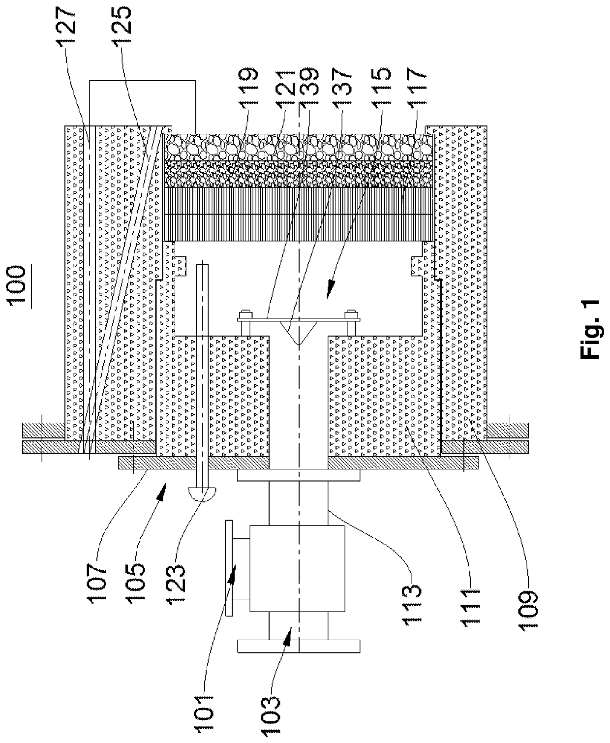
The present disclosure provides a porous medium premixing combustor that can efficiently and cleanly combust fuels, be adaptable to different gas calorific values, and prevent backfire while facilitating flame monitoring and predicting and monitoring the use status of the porous medium material in real time. The combustor features an air-fuel gas mixer, combustor body with a thermocouple, inner burner block, and detecting electrode, and a mixed gas distributing plate, ordered porous plate, small-pore foamed ceramic plate, and big-pore foamed ceramic plate sequentially provided inside the square chamber. The key technical effects include uniform distribution of mixed gas in the whole porous medium, effective prevention of backfire, monitoring and controlling combustion condition in a preheating space, and efficient and safe operation of the combustor.

Problems solved by technology

Currently in our country, a main combustion manner is space combustion featured by free flame, with a series of defects such as emission of more nitrogen oxides caused by a too high local flame temperature, a large volume occupied, low combustion efficiency, and incapability of combusting low-calorific-value gases.
However, the porous medium combustion technology has not been widely applied in industrial production due to various limitations.
According to reports, porous medium combustors that have been applied in industry are mostly limited to the field of heating at low temperatures such as papermaking, textile, and drying, while studies on porous medium combustors for the field of heating at moderate and high temperatures mostly focus on experimental studies, and have not been widely applied in industry yet.
However, as the porous medium combustion technology is being popularized to the field of heating at moderate and high temperatures, arrangement of such porous medium layer with a single pore size is no longer applicable, with specific defects represented as follows:
(1) It is impossible to predict and effectively prevent backfire (there are unstable phenomena such as flame quenching, backfire, and flame deflection):
However, when the porous medium combustor is applied to the field of heating at moderate and high temperatures, the porous medium as a whole is in a relatively high temperature environment (locally exceeding 1400° C. or even higher when a high-calorific-value gas is combusted) due to a relatively high heat load per unit area of the porous medium, and more heat refluxes through the porous medium to the uncombusted premixed gas.
In the event of long-term operation or a sudden change in the combustion condition, there may be a situation where a pore structure of the porous medium material is damaged under a high temperature, especially pores of a small-pore porous medium are more easily to be damaged, and heat refluxing to the uncombusted premixed gas is suddenly increased.
When such situation is aggravated continuously, a phenomenon that an electrode can detect a flame signal but backfire occurs to the combustor takes place.
Therefore, a control idea of determining whether there is a backfire or not simply dependent on detecting flame by an electrode is no longer applicable.
As the flame temperature increases, a medium effective radiation coefficient will increase by times of third power of the temperature, and reinforced heat regenerating is likely to cause backfire.
(2) It is impossible to predict and monitor use status of the porous medium material in real-time:
In long-term use, situations such as aging of the material and damage of the pore structure will be inevitably encountered.
When the material is damaged to a certain extent, the small-pore area loses a barrier function for preventing backfire, and backfire occurs to the combustor, which is even worse when it is applied to the field of heating at moderate and high temperatures.
However, such situation is not taken into consideration or monitored for existing porous medium combustors, seriously affecting use effects.
(3) When air and a fuel gas are preheated by the combustor, it is impossible to monitor a real-time operating condition (there is no premixing temperature detection device):
Once the heat is superimposed such that the temperature of the gas reaches a certain value inside a premixing chamber, even a backfire explosion will be caused, and a safety accident will occur.
In an actual process, the gas is generally preheated by using a heat exchanger, and a heat source is combusted waste gas, while the current design level of heat exchangers generally cannot achieve precise control over the temperature, and the combusted waste gas may also fluctuate at any time.
All these factors will cause the gas preheated by the heat exchanger to be unable to reach or exceed a design temperature, and a backfire explosion accident occurs.
For diffusion combustion, a sudden change in the preheating temperature will raise the temperature of the flame in the combustion zone of the porous medium, and accelerate the damage of the porous medium.

Method used


Image

  • Porous medium premixing combustor
  • Porous medium premixing combustor
  • Porous medium premixing combustor

Examples


Embodiment Construction

[0028]In order to make the objects, technical solutions, and advantages of the embodiments of the present disclosure much clearer, below the technical solutions in the embodiments of the present disclosure will be described clearly and completely in conjunction with the accompanying drawings in the embodiments of the present disclosure, apparently, some but not all embodiments of the present disclosure are described. Generally, components in the embodiments of the present disclosure, as described and shown in the accompanying drawings herein, may be arranged and designed in various different configurations. Therefore, the detailed description below of the embodiments of the present disclosure provided in the accompanying drawings is not intended to limit the scope of protection of the present disclosure claimed, but merely illustrates chosen embodiments of the present disclosure. On the basis of the embodiments of the present disclosure, all of other embodiments, obtained by a perso...


PUM

PropertyMeasurementUnit
pore equivalent diameteraaaaaaaaaa
temperaturesaaaaaaaaaa
temperatureaaaaaaaaaa

Abstract

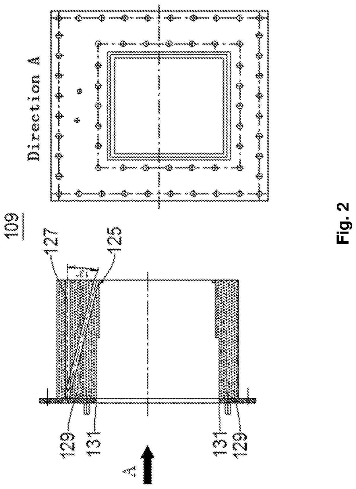
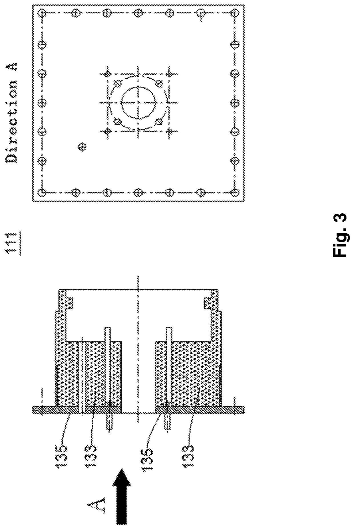
A porous-medium premixing combustor is provided, which includes: an air-fuel gas mixer, a combustor body, a thermocouple, an ignition electrode, and a detecting electrode. The combustor body includes a casing connected to the air-fuel gas mixer; an outer and an inner burner-block, wherein the outer burner-block and the casing are connected, forming a square chamber, and the inner burner-block is provided inside the square chamber, with a via hole communicating with a pipe; and a mixed gas distributing plate, an ordered porous plate, a small-pore foamed ceramic plate, and a big-pore foamed-ceramic plate sequentially provided along an axis direction of the via hole of the inner burner-block. The thermocouple is provided at the casing and extends into the square chamber. The ignition electrode is provided close to an end of the big-pore foamed-ceramic plate. The detecting electrode is provided close to an exit end of the big-pore foamed-ceramic plate.

Description

CROSS-REFERENCE TO RELATED APPLICATIONS[0001]This application claims priority to Chinese Patent Application No. CN201810466435.3, filed on May 15, 2018 with the Chinese Patent Office and entitled “Porous Medium Premixing Combustor”, the content of which is herein incorporated by reference in its entirety.TECHNICAL FIELD[0002]The present disclosure relates to the technical field of premixing combustion, particularly to a porous medium premixing combustor.BACKGROUND OF THE INVENTION[0003]With the development of society and ever-decreasing fossil energies such as coal and petroleum, people are increasingly aware of broadening energy utilization and saving energy and reducing emission. Currently in our country, a main combustion manner is space combustion featured by free flame, with a series of defects such as emission of more nitrogen oxides caused by a too high local flame temperature, a large volume occupied, low combustion efficiency, and incapability of combusting low-calorific-va...

Claims


Application Information

Patent Timeline
Patent Type & Authority Patents(United States)
IPC IPC(8): F23D14/66F23D14/70F23D14/14F23D14/02F23C1/06B01F5/06B01F3/02B01F15/00B01F23/10
CPCF23D14/70B01F3/02F23C1/06F23D14/66B01F15/00915F23D14/14B01F5/0691F23D14/02F23N2239/04B01F2215/0086F23N2227/02F23N2225/20F23N2229/00F23D14/46F23D14/48F23D14/725F23D2212/101F23D2203/105F23D14/145B01F35/55F23D14/16Y02E20/34B01F23/10B01F25/4522B01F2101/503
Inventor CHEN, YUANYUANXU, XUECHENGLI, BINLI, BENWENHE, ZHULI, YAWEILIANG, XIONG
Owner WUHAN UNIV OF SCI & TECH
Learn More