Storage device, its controlling method, and storage system having the storage device

a storage device and control method technology, applied in the direction of storage address/allocation/relocation, instruments, input/output to record carriers, etc., can solve the problems of excessive use of buffer memory bandwidth, storage data is likely to be destructed, and the amount of data inputted to and outputted from the buffer memory can be efficiently reduced, and the performance of the buffer memory is affected. , to achieve the effect of reducing the amount of data input and output, and reducing the performance of the bottl

Active Publication Date: 2020-10-13
HITACHI LTD
View PDF10 Cites 0 Cited by
  • Summary
  • Abstract
  • Description
  • Claims
  • Application Information

AI Technical Summary

Benefits of technology

[0020]According to the present invention, the amount of data inputted to and outputted from the buffer memory can be efficiently reduced, and a bottleneck in performance due to the excessive use of the bandwidth of the buffer memory can be improved, so that the lowering of the performance of the storage device can be effectively prevented.

Problems solved by technology

When the data compression is performed, the logical data length becomes short to cause displacement from the size of the physical page that is a unit for actually writing data.
Due to this, although a plurality of compressed data can be stored in one physical page, there is the case where the compressed data cannot be accommodated within one physical page.
In addition, the flash memory has, due to its physical characteristic, properties in which stored data is likely to be destructed.
When this method is applied to the SSD, the data length of each code word actually stored in the flash memory is changed according to the strength of the ECC, and with this, the data length of the entire writing target data is changed, so that size deviation occurs between the data length and the physical page, with the result that the page straddling may occur.

Method used


Image

  • Storage device, its controlling method, and storage system having the storage device
  • Storage device, its controlling method, and storage system having the storage device
  • Storage device, its controlling method, and storage system having the storage device

Examples


first embodiment

(1) First Embodiment

[0045](1-1) The Configuration of a Computer System According to this Embodiment

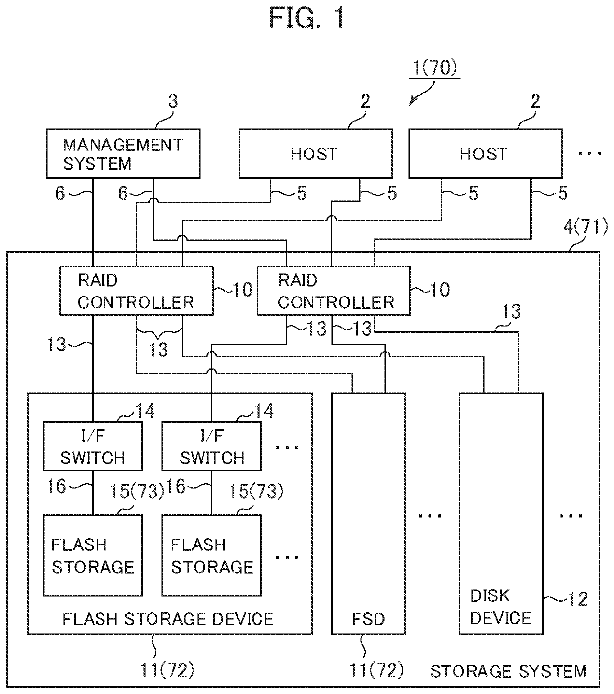
[0046]FIG. 1 illustrates a configuration example of a computer system according to this embodiment. A computer system 1 has one or a plurality of host computers (hereinafter, called a host or hosts) 2, a management system 3, and a storage system 4.

[0047]The at least one host 2 is a computer device having an information processing resource, such as a CPU (Central Processing Unit) and a memory, and includes a personal computer, a workstation, a main frame, and the like. The host 2 has a communication port for connecting the host 2 to the storage system 4, the port being connected to the storage system 4 via a host connection path 5.

[0048]Likewise, the management system 3 is a computer device having an information processing resource, such as a CPU and a memory, and includes a personal computer, a workstation, a main frame, and the like. The management system 3 further has a port for conn...

second embodiment

(2) Second Embodiment

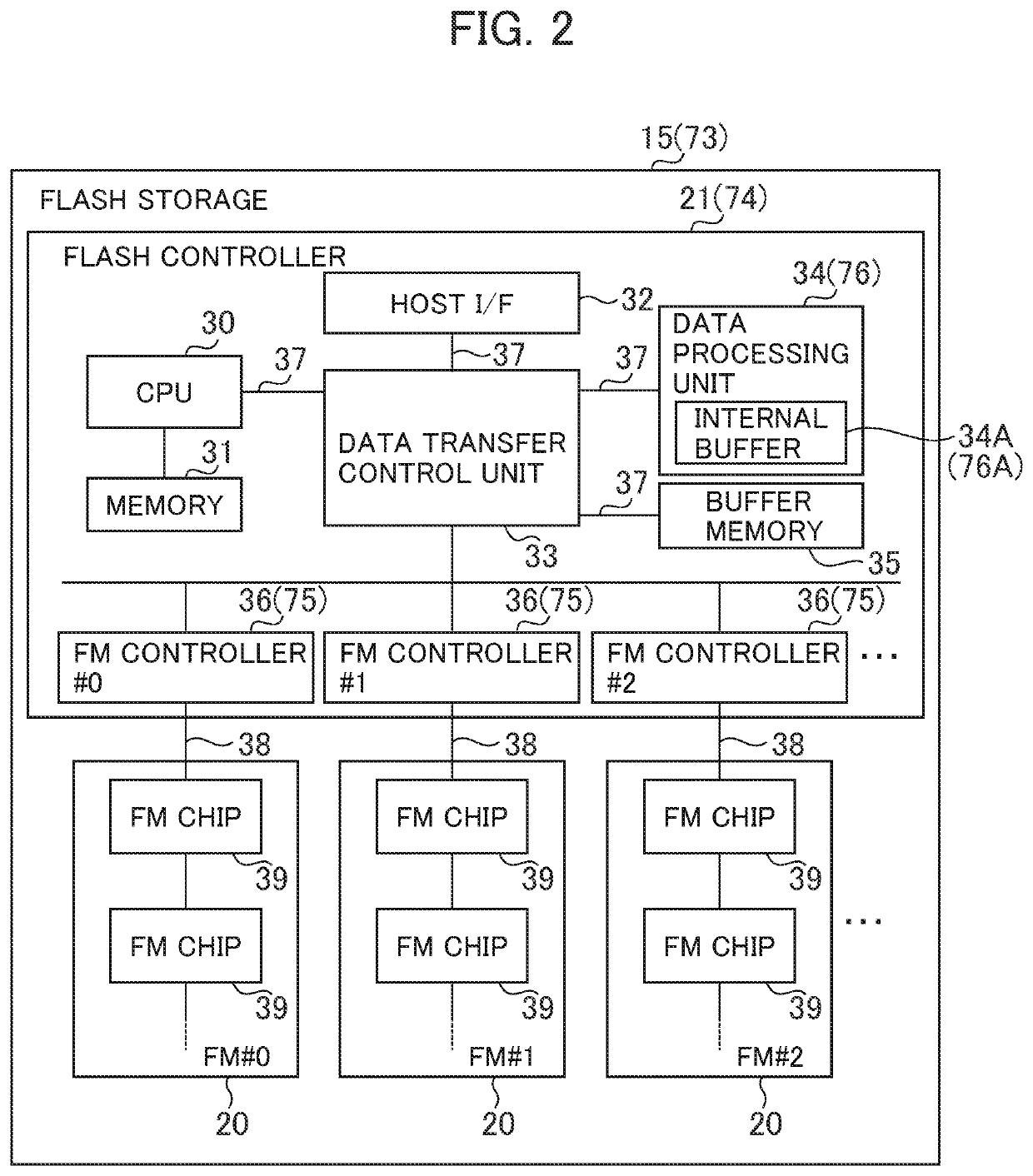
[0138]In FIG. 1, the reference sign 70 denotes a computer system according to a second embodiment in its entirety. The computer system 70 is different from the computer system 1 according to the first embodiment in that each flash memory controller 75 (FIG. 2) of a flash storage 73 (FIG. 2) executes the ECC process for adding an ECC to writing target data by using the ECC circuit 61 (FIG. 6) provided in the interior of the flash memory controller 75, and the error correction process for correcting, based on the ECC given to read-out data, the error of the read-out data, as needed.

[0139]In addition, the computer system 70 according to this embodiment is also different from the computer system 1 according to the first embodiment in that the data processing unit 76 (FIG. 2) of the flash storage 73 subjects writing target data and read-out data to other data processes except for the data compression process and the data extension process. Although in the following d...


PUM


Abstract

A storage device determines whether or not reading target data subjected to a first conversion process is divided and stored into multiple pages. When the data subjected to the first conversion process is stored in one of a plurality of pages, the data is read from the page, and a second conversion process for returning the data to a state before the data is subjected to the first conversion process is executed to the data. When the reading target data is divided and stored into two or more of the plurality of pages, a portion of the data is read from each of the two or more pages in which the portion of the data is stored, the portion of the data is stored in the buffer memory, the data subjected to the first conversion process is restored, and the second conversion process is executed to the restored data.

Description

TECHNICAL FIELD[0001]The present invention relates to a storage device, its controlling method, and a storage system having the storage device.BACKGROUND ART[0002]As semiconductor storage devices that enable high-speed access, SSDs (Solid State Drives) have been in widespread use recently. Such a semiconductor storage device has a hardware architecture that has a plurality of nonvolatile semiconductor memory chips in the device and drives the memory chips in parallel. Only the number of semiconductor memory chips connected by buses can be operated in parallel, so that the operation of the memory chips in parallel can achieve high input-output performance. As compared with a hard disk drive (HDD: Hard Disk Drive) that is a conventional magnetic storage device, the semiconductor storage device has the merit of improving performance by the parallelization of the semiconductor memory chips, of being capable of coping with partial failure, and of being capable of easily designing perform...

Claims


Application Information

Patent Timeline
Patent Type & Authority Patents(United States)
IPC IPC(8): G06F3/06G06F12/02G06F12/1009
CPCG06F12/0246G06F12/1009G06F3/0689G06F3/0679G06F3/0656G06F3/061G06F3/0661G06F3/0688G06F2212/401G06F2212/403G06F2212/7201G06F2212/402G06F3/067
Inventor FUJII, HIROKIKOSEKI, HIDEYUKIKAWAMURA, ATSUSHI
Owner HITACHI LTD
Why Eureka
Try Eureka